
HR Diemen
An inverter, also known as an ondulator, is an electronic circuit designed to convert direct current (DC) into alternating current (AC). Its primary function is to alter the input voltage of direct current—typically sourced from a 12 or 24 V DC battery—to an output voltage that corresponds to standard AC voltage levels, usually 110 or 230 V AC.
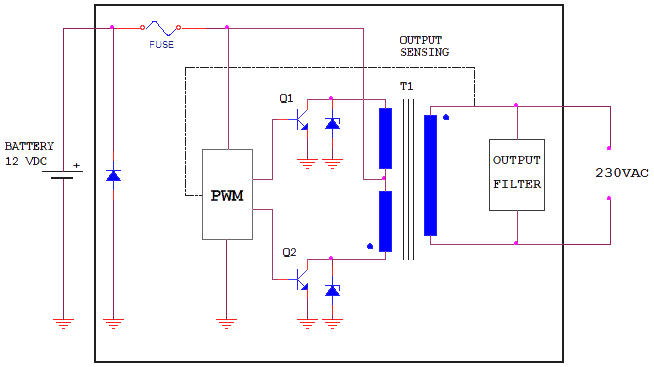
Inverters typically consist of an oscillator that controls a transistor, which interrupts the steady input voltage to generate a square wave. This square wave is then fed into a transformer that adjusts the voltage level at the output, while a final filter smooths the waveform to resemble a pure sine wave. It is also possible to produce a modified sine wave, which is generated from three reference points: one positive, one negative, and one grounded. Modified sine wave inverters may exhibit reduced efficiency, particularly when powering inductive loads.
Power peaks are significant for certain equipment, such as motors, which require an initial surge of power upon connection. Once the equipment is running continuously, the power consumption typically decreases, allowing for stable operation. The input voltage range indicates the voltage variation from the source (battery) that the inverter can accommodate; if the voltage falls below a minimum threshold or exceeds a maximum threshold, the inverter will cease to provide power. Total Harmonic Distortion (THD) measures the harmonic distortion present in the signal, defined as the ratio of the sum of the power of all harmonic components to the power of the fundamental frequency.
Inverters are fundamental components in various applications, including renewable energy systems, uninterruptible power supplies (UPS), and motor drives. The design of an inverter circuit must consider several parameters, including efficiency, output waveform quality, and load compatibility. The oscillator circuit often employs a feedback mechanism to regulate the output frequency and amplitude, ensuring stable operation under varying load conditions. The transformer used in the inverter should be appropriately rated for the desired output power and voltage levels, and the filter stage may include capacitors and inductors to minimize ripple and harmonics in the output waveform.
Furthermore, the choice of transistors (such as MOSFETs or IGBTs) is critical to the inverter's performance, as they must handle the required switching speeds and current ratings. Protective features, such as over-voltage, over-current, and thermal protection, are essential to safeguard the inverter and connected loads from potential damage during operation. Overall, the design and implementation of an inverter circuit require careful consideration of electrical characteristics, component ratings, and operational requirements to ensure reliability and efficiency in converting DC to AC power.Inverter or ondulator, is an electronic circuit used to turn direct current (DC) into alternating current (AC). The function of an inverter is to change the voltage of entry of direct current (it normally comes from a battery of 12 or 24 Vdc) to an alternate voltage of exit (normally tension of network (net) 110 or 230 Vac).
The inverters are in the habit of being composed of an oscillator that controls a transistor wich is used to interrupt the constant tension of entry and to generate a square wave. This square wave feeds a transformer that adapts the tension level wiched in the exit and a final filter smooth the waveform making it very similar to a pure sine wave.
It is also possible to generate modified sine wave, wich is generated from three points: one positive, the negative one and one to ground. Modified since wave inverters can cause less efficiency especially when working with inductive loads.
Peak of Power. - Some equipments as, for example those who take an engine, they need an increase of power when being connected. Once the equipment is in a permanent way the consumed power is minor and can continue operating in constant way.
Input voltage range. - It is the voltage variation of the source (battery) that the inverter admits to work; below the minimal voltage and over the maximum voltage the inverter will stop giving power. THD (Total Harmonic Distorsion). - Of a signal, it is the measure of the harmonic present distortion in the signal and there is defined as the relation between the sum of the power of all the harmonic components and the power of the fundamental frequency.
🔗 External reference