
Human-Computer Interface Technology 2
Prototype 2 is designed as a versatile electronic instrument that integrates various control mechanisms to enhance user interaction. The addition of a button allows for dynamic sound production, enabling tones to be generated only when the button is pressed. This feature adds an element of playability, making it suitable for different performance scenarios, whether solo or in a group setting.
The rotary potentiometer serves as a volume control, allowing users to adjust the audio output level easily. This component is vital for tailoring the listening experience, particularly in collaborative performances where multiple players may have different preferences for sound intensity.
The core of the prototype is the ADXL3xx accelerometer, which measures acceleration along three axes (x, y, and z). The accelerometer's readings are transmitted to a microcontroller, which processes the data to produce sound. The schematic indicates the connections between the accelerometer and the microcontroller, utilizing specific analog pins for power, ground, and data acquisition. The pin assignments ensure that the accelerometer operates correctly within the circuit, allowing for accurate readings.
The code implementation includes a setup function that configures the necessary pins for operation and initializes serial communication for data output. The loop function continuously reads the accelerometer values and calculates a cumulative frequency based on the x, y, and z readings. This frequency is then used to generate a tone through a buzzer connected to a designated output pin.
While the instrument is limited in terms of interaction range due to its stationary design, it offers a unique platform for musical exploration. The concept of using each prong to control different sound parameters encourages creativity and collaboration among players. Future iterations of the project may incorporate motion sensors to allow for a more dynamic playing experience, further expanding the instrument's capabilities. Overall, this prototype represents an innovative approach to interactive sound generation, combining electronics with musical expression.Prototype 2 uses the same base to control different elements. This time we have added a button to make the tone play only when it is pressed, as well as a rotary potentiometer for volume control. /* ADXL3xx Reads an Analog Devices ADXL3xx accelerometer and communicates the acceleration to the computer.
For AdaFruit ADXL335 breakout board. Modified from code at The circuit: analog 0: Vin analog 1: 3vo analog 2: ground analog 3: z-axis analog 4: y-axis analog 5: x-axis test pin is hanging off the edge :) created 2 Jul 2008 by David A. Mellis by Tom Igoe modified 19 Feb 2013 by Rebecca Fiebrink This example code is in the public domain.
*/ // these constants describe the pins. They won`t change: const int groundpin = A2; // analog input pin 2 const int powerpin = A0; // analog input pin 0 const int xpin = A5; // x-axis of the accelerometer const int ypin = A4; // y-axis const int zpin = A3; // z-axis void setup() { // initialize the serial communications: Serial. begin(9600); // Provide ground and power by using the analog inputs as normal // digital pins. This makes it possible to directly connect the // breakout board to the Arduino. If you use the normal 5V and // GND pins on the Arduino, you can remove these lines. pinMode(groundpin, OUTPUT); pinMode(powerpin, OUTPUT); digitalWrite(groundpin, LOW); digitalWrite(powerpin, HIGH); } void loop() { // print the sensor values: Serial.
print(analogRead(xpin); // print a tab between values: Serial. print(" "); Serial. print(analogRead(ypin); // print a tab between values: Serial. print(" "); Serial. print(analogRead(zpin); Serial. println(); int xfreq = analogRead(xpin); int yfreq = analogRead(ypin); int zfreq = analogRead(zpin); tone(8, xfreq+yfreq+zfreq); // delay before next reading: delay(100); } Our group built a an instrument that can be played by 1-3 people. Our inspiration was essentially creating a musical Bop-It. Each end of the three-prong instrument has a different control over the sound. We liked that the instrument can be played by a range of people, our project can be the basis for a solo, duet, or trio piece.
The device is limited in the range of interactions. While there are multiple useful controls, each sits on the unmoving object. With one more iteration we may have included the accelerometer to make a moving object. Additionally, we can only play within one octave because of limitations with the size of the Overall, we found the final product a fun and interesting challenge for multiple players. In this instrument, as mentioned before, each prong of the frisbee controls a different musical aspect of the sound that the buzzer plasimple testing sketch) { slideReading = analog(buttonPin); if (button last prototype, made aport time ser = serianext reading: double diff = fabs(analogRead(xpin) - BASELINE); if (diff 950, 1023, 1023, 320}; The player holds each piece in a hahe slider position ( delay(50); }
🔗 External reference
Related Circuits
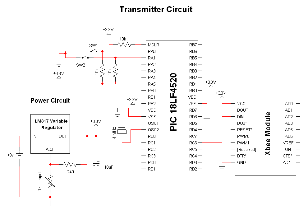
The advantage of these compact Xbee modules is that they handle most of the complex tasks. The transmitter and receiver circuits are both straightforward. The primary components in the circuit include the Xbee Modules, PIC 18LF452, and LM317. Both...
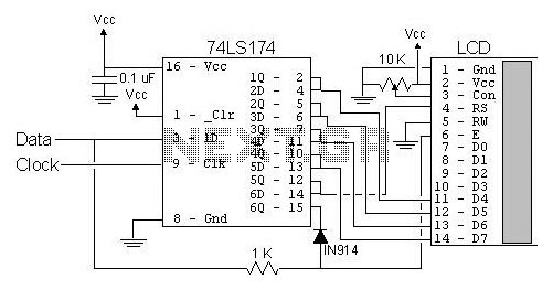
The most popular LCD interface is the Hitachi 44780 based LCD controller chip which provides a fairly easy to work with interface and low power consumption. The major drawback of the interface is the perceived complexity of working with...
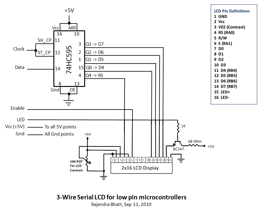
Library routines for a 3-wire LCD interface utilizing the 74HC595 shift register. Additional details can be found in the attached ReadMe document or on the associated webpage. The library routines for the 3-wire LCD interface are designed to facilitate communication...
Below are three examples of controlling a relay from the PC's parallel printer port (LPT1 or LPT2). Figure A shows a solid state relay controlled by one of the parallel port data lines (D0-D7) using a 300 ohm resistor...
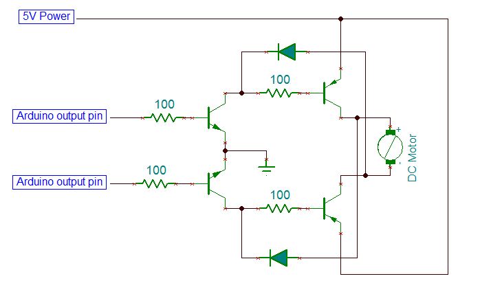
On the breadboard, construct two bi-directional motor control circuits, commonly referred to as "H-bridge" circuits. These circuits will manage the two DC motors that propel the wheels. Each circuit will have two wires connected to the Arduino (one for...
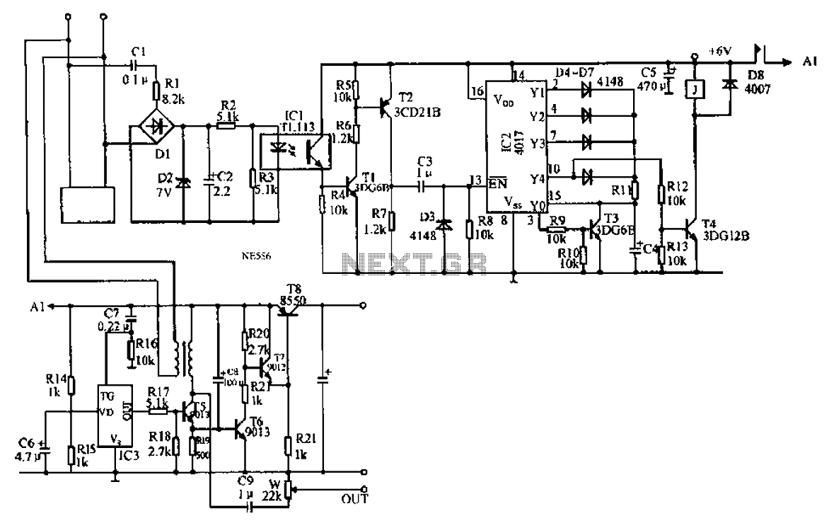
An automatic recording telephone interface circuit is presented, featuring an automatic answering and recording function that requires a reprovisioning or a small solid-state recording chip. The circuit is straightforward, with a quiescent current of less than 20 µA, allowing...
Warning: include(partials/cookie-banner.php): Failed to open stream: Permission denied in /var/www/html/nextgr/view-circuit.php on line 713
Warning: include(): Failed opening 'partials/cookie-banner.php' for inclusion (include_path='.:/usr/share/php') in /var/www/html/nextgr/view-circuit.php on line 713