
Hybrid-power-amplifier
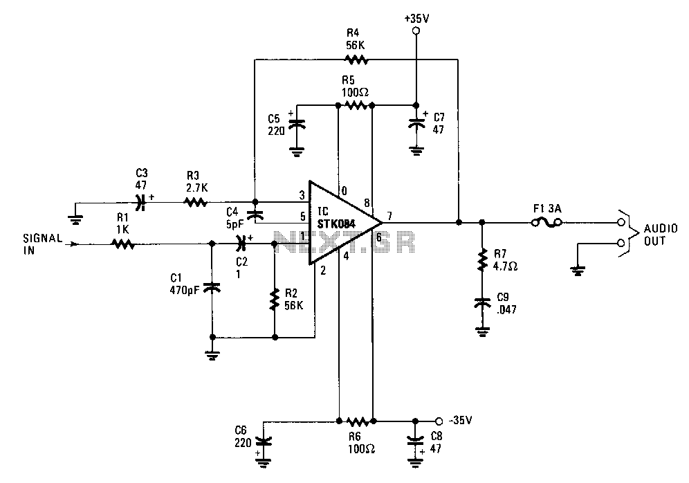
The input is AC coupled to the amplifier through capacitor C2, which blocks any DC signals that may also be present at the input. The combination of resistor Rl and capacitor Cl forms a low-pass filter, effectively eliminating unwanted high-frequency signals by directing them to ground when they appear at the circuit input, which has an impedance of approximately 52 ohms. The gain of the amplifier is set to around 26 dB by resistors R3 and R4. The combination of R5, C5, and C7 on the positive supply, along with R6, C6, and C8 on the negative supply, provides power-supply decoupling. Resistor R7 and capacitor C9 work together to prevent oscillation at the amplifier's output.
From this point, the amplifier's output signal is directly coupled to the speaker through a 3-A fuse, F1. The DC output of the amplifier at pin 7 is 0 V, ensuring that no DC current flows through the speaker. In the event of a catastrophic failure of the output stage, fuse F1, which should be of a fast-acting type, prevents DC from flowing through the speaker.
The circuit design effectively integrates several critical components to ensure optimal performance and reliability. The AC coupling through capacitor C2 is crucial for isolating the amplifier from any DC offset present at the input, allowing only the intended AC signal to pass through. The low-pass filter formed by Rl and Cl is essential for maintaining audio fidelity by filtering out high-frequency noise that could distort the output signal.
The gain configuration using resistors R3 and R4 is designed to achieve a specific amplification level of approximately 26 dB, which is suitable for driving the connected speaker without introducing unwanted noise or distortion. The power-supply decoupling achieved by the R5/C5/C7 and R6/C6/C8 pairs is critical for minimizing the impact of power supply fluctuations on the amplifier's performance, ensuring stable operation under varying load conditions.
Additionally, the inclusion of R7 and C9 at the output stage serves as a precautionary measure against oscillations, which can lead to instability in the amplifier and potentially damage the connected speaker. The direct coupling of the output to the speaker through a fast-acting fuse F1 is a safety feature that protects the speaker from damage in the event of an output stage failure, ensuring that any excessive current is interrupted promptly.
Overall, this circuit design exemplifies a thoughtful approach to audio amplification, balancing performance, safety, and reliability through the careful selection and arrangement of components.The input is ac coupled to the amplifier through C2, which blocks de signals that might also be present at the input. The Rl/Cl combination forms a low-pass filter, which eliminates unwanted high-frequency signals by bypassing them to ground when they appear at the circuit input, which has an impedance of about 52 0.
The gain of the amplifier is set at about 26 dB by resistors R3 and R4. The R5/C5/C7 combination on the positive supply and its counterpart R6/C6/C8 on the negative supply provides power-supply decoupling. R7 and C9 together prevent oscillation at the output of the amplifier. From that point, the amplifier"s output signal is direct coupled to the speaker through a 3-A fuse, Fl. The de output of the amplifier at pin 7 is 0 V, so no de current flows through the speaker. Should there be a catastrophic failure of the output stage, fuse Fl, which should be a fast -acting type, prevents de from flowing through the speaker.
🔗 External reference
Warning: include(partials/cookie-banner.php): Failed to open stream: Permission denied in /var/www/html/nextgr/view-circuit.php on line 713
Warning: include(): Failed opening 'partials/cookie-banner.php' for inclusion (include_path='.:/usr/share/php') in /var/www/html/nextgr/view-circuit.php on line 713