
I.F. Amplifier
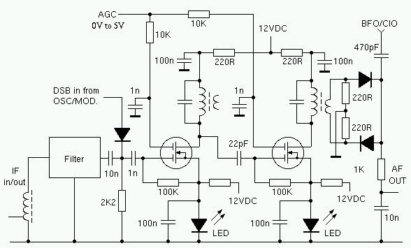
The Intermediate Frequency (I.F.) amplifier described is a critical component in radio receiver systems, particularly for the 80M band. The modification involving the inclusion of Light Emitting Diodes (LEDs) in the source circuit of each MOSFET is notable for enhancing the performance of the amplifier. The LEDs introduce a fixed voltage drop, stabilizing the source voltage at approximately 2 volts. This stabilization is essential for achieving a broader Automatic Gain Control (AGC) range, which is crucial for maintaining signal integrity across varying input levels.
In this design, the I.F. transformer plays a pivotal role in signal processing. The primary winding consists of 18 turns, while the secondary winding features 4 turns. This specific turn ratio is indicative of the desired impedance transformation and voltage gain characteristics of the amplifier. The 18:4 turn ratio implies that the primary winding is designed to handle a higher voltage from the preceding stages, while the secondary winding steps down the voltage to a level suitable for further amplification or processing.
The choice of MOSFETs in this I.F. amplifier design is likely due to their high input impedance and fast switching capabilities, which are advantageous in high-frequency applications. The incorporation of the LEDs not only aids in voltage stabilization but also potentially provides visual feedback for circuit operation, allowing for easier troubleshooting and performance monitoring.
Overall, the modifications and design choices made in this I.F. amplifier reflect a thoughtful approach to enhancing receiver performance, ensuring that it can effectively manage signal variations and maintain clarity in communication.The I.F. amplifier is similar to the one used in the 80M receiver project . The original design has been modified by putting a couple of LED`s in the source circuit of each Mosfet. The voltage drop across the LED`s keeps the source voltage at about two volts. This results in a much greater AGC range. This arrangement was suggested by N6BIU. Thanks Jim. The I.F. transformer primary has 18 turns, the secondary winding has 4 turns. 🔗 External reference
Related Circuits
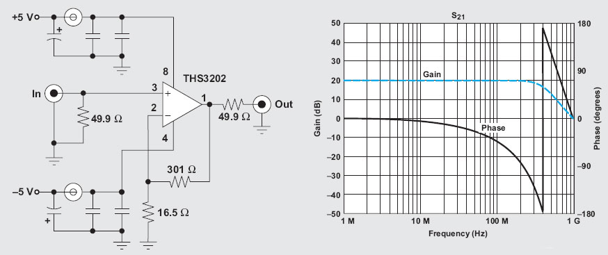
The operational amplifier (op-amp) has a significant history, particularly with the 741/301 series, which has been popular for approximately 20 years due to its ease of calculation (gain calculation), affordability, and simplicity of construction. The versatility of op-amps allows...
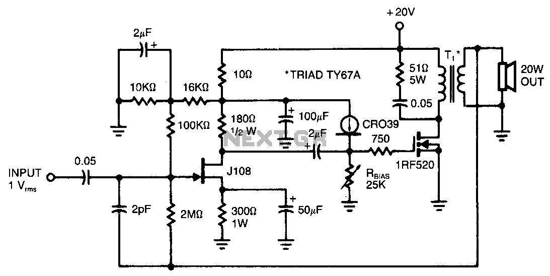
This amplifier provides 20 W of power to an 8-ohm load utilizing a single IRF520 transistor driving a transformer-coupled output stage. The design resembles the audio output stages commonly found in many low-cost radios and phonographs. Distortion remains below...
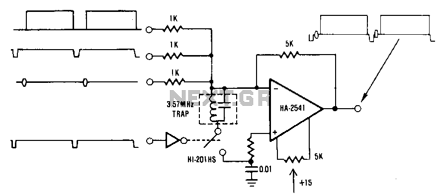
This circuit is a conventional summing amplifier configuration that incorporates a de-clamping circuit. The operation is straightforward; each component—synchronization, color burst, picture information, etc.—of the composite video signal is connected to its respective input terminal of the amplifier. These...
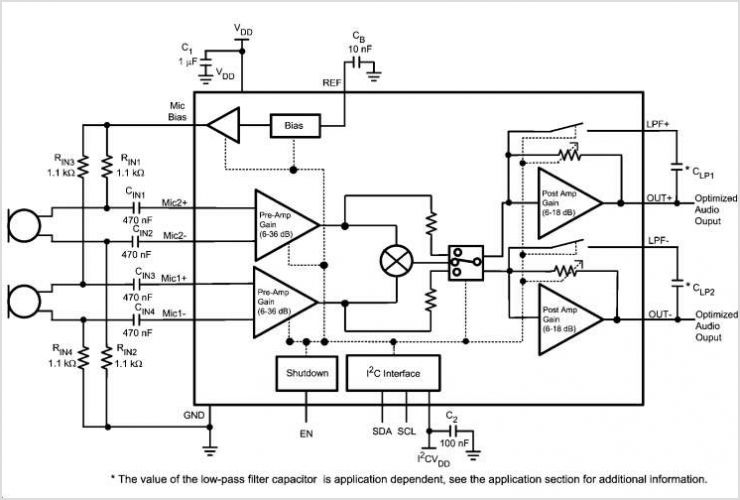
Figure 1 illustrates the schematic for a universal input, 7.6 V, 700 mA constant voltage/constant current (CV/CC) power supply designed for LED driver applications. This design employs the LinkSwitch-II product LNK606PG in a flyback configuration. The LNK606PG (U1) integrates...
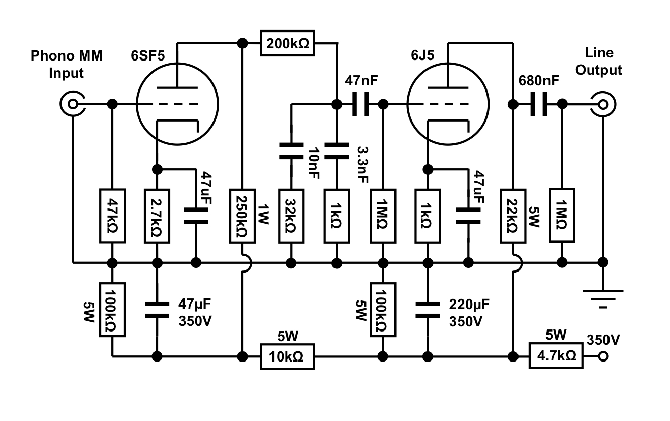
An octal preamplifier can be constructed as a standalone unit without the linestage component. However, this is not feasible due to its split RIAA configuration, which divides the RIAA equalization circuit into two sections: one following the first stage...
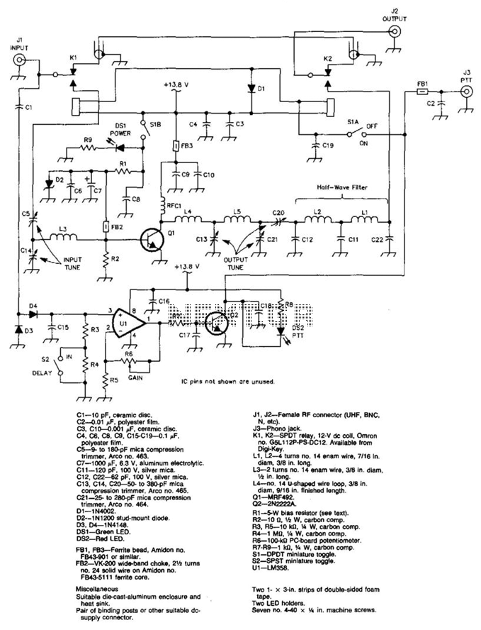
A 100 W output at 50 MHz is available from this circuit. U1 and Q2 form a T-R relay driver, switching the amplifier on when RF input at J1 is sensed. During receive periods, J1 and J2 are directly...
Warning: include(partials/cookie-banner.php): Failed to open stream: Permission denied in /var/www/html/nextgr/view-circuit.php on line 713
Warning: include(): Failed opening 'partials/cookie-banner.php' for inclusion (include_path='.:/usr/share/php') in /var/www/html/nextgr/view-circuit.php on line 713