
IC 723 Power Supply Circuit with Current Indicator
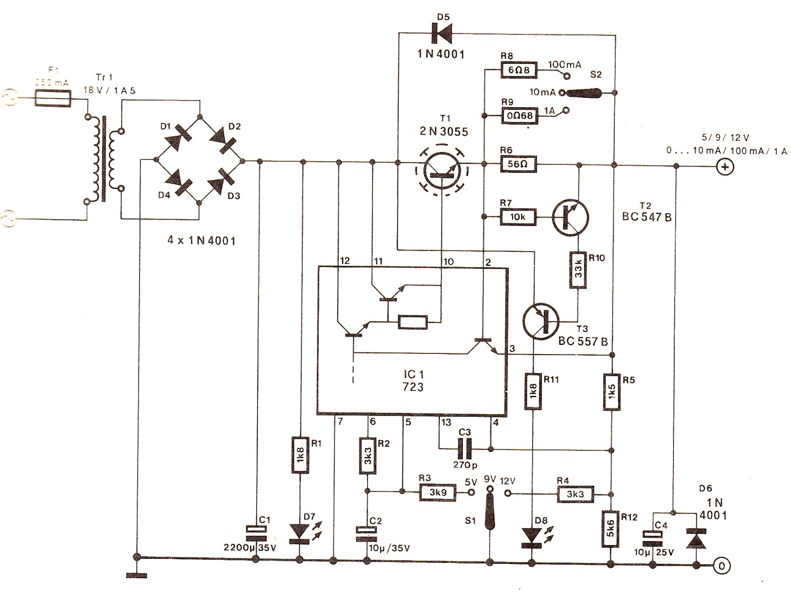
The described circuit is an adjustable power supply system capable of producing multiple output voltages suitable for a variety of electronic applications. The ability to increase the output voltage to 5.0 V through the addition of a parallel resistor with Ra allows for fine-tuning of the voltage level, which is critical for precision applications. The choice of SPDT switches S1 and S2, or alternative rotary switches, provides flexibility in circuit design while ensuring that the center contact remains unused to avoid unintended circuit behavior.
The integration of an external transistor for overcurrent indication introduces complexity to the circuit, as it necessitates careful matching of transistor characteristics to ensure reliable operation. The potential inaccuracies in output voltage due to the use of E12 series resistors highlight the importance of selecting components with tight tolerances, especially in the critical 5 V output range. The specified output voltages (5 V, 9 V, and 12 V) cater to a wide range of applications, from digital logic circuits to communication interfaces, demonstrating the versatility of the power supply.
The current limiting feature, adjustable to various levels, enhances the safety and usability of the power supply for experimental circuits. The design also emphasizes thermal management through the use of an adequately sized heat sink for the power regulator T1, which is essential for maintaining stable operation under load conditions. The inclusion of LED indicators for power status and overload conditions provides immediate visual feedback, aiding in the monitoring and troubleshooting of the circuit.
Overall, this power supply design exemplifies a well-thought-out approach to providing reliable and adjustable voltage outputs for diverse electronic applications, incorporating essential features such as current limiting, thermal management, and user-friendly indicators.This can be. increased readily by fitting a resistor in parallel with Ra, until the output voltage is5. 0 V precisely Switches S1 and Sz are preferably SPDT types with a centre position, but three-way rotary switches should also do if in both cases the centre contact is not used. A difficulty arises if it is intended to provide an overcurrent indi cation for the shutdown circuit with the aid of an external transistor fitted in parallel onto pins 2 and 3, since the external and internal transistor are highly unlikely to have precisely the same characteristics. The output voltages of the supply may not be as accurate as required, and this is mainly due to the use of resistors from the E12 series.
Close tolerance is especially important in the 5 V range, since the value shown for R3 gives a theoretical output of 4. 9 V The three output voltages from this supply are probably the, most commonly used for testing asymmetrically fed designs: 5 volt for many TTL and CMOS circuits, 9 volt for battery operated equipment or logic circuits equipped with a 7805 regulator (this requires, an input of at least 8.
5 V), and 12 volt for RS232 drivers, and miscellaneous opamp or tran- sistor based circuits. Since the base-emitter junction then has a diode characteristic, the associated voltage drop is always lower than that of the transistor internal to the 723. The current limiter can be set to l0 mA, 100 mA, or l A for safely power- ing- experimental circuits.
Power regulator T1 should be fitted with a heat sink sized at least l0 >< 10 cm. LEDs Dv (green) and Ds (red) are the power on and current overload indicator, respectively. When the internal transistor has the low B ”E voltage of the two, the indication will not work, while in the other case the external transistor takes away the base current for the internal transistor, so that the current limiter is rendered ineffective. In this design of a power supply, a current overload indication was realized by fitting the external transistor with a high value base resistor, Rv, to ensure that the current limiter in the 723 is not disabled.
🔗 External reference
Related Circuits
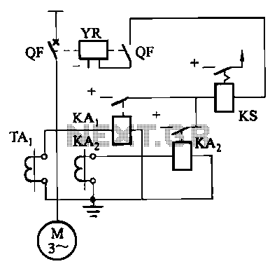
Figure 4-52 (a) illustrates the two-phase wiring for direct current (DC) operation, while Figure 4-52 (b) depicts the two-phase current differential wiring for alternating current (AC) operation. The schematic in Figure 4-52 (a) represents a two-phase wiring configuration suitable for...
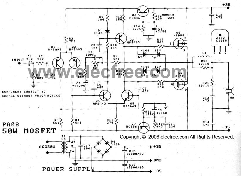
The 50W Power Amplifier OCL Mosfet (K1058 + J162) is simple to construct and cost-effective. It requires a power supply of +35V and -35V at 2A. The Power Mosfet used in this design is K1058 and J162. The 50W OCL...
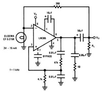
This device has a quiescent power drain of 24 milliwatts when operating from a 6 V supply, making the LM386 ideal for battery operation. According to the application hints section of the LM386 datasheet, two pins (1 and 8)...
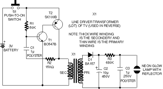
This circuit operates on 12V DC instead of mains AC. This is an advantageous approach for those who prefer not to deal with circuits connected directly to mains voltage or wish to power the stroboscope using batteries. Flash Slave...
Basic information on the construction of various types of lasers from scratch, including topics such as home-built laser safety, setting up a home laser lab, sources of supplies and chemicals, vacuum systems, glass working, structural materials, power supplies, and...
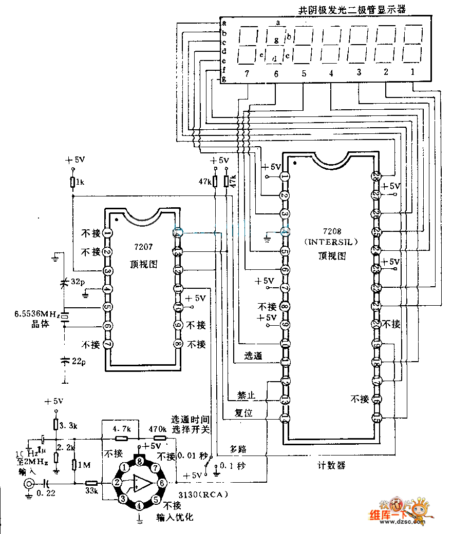
The 7208 seven-stage decimal counter can be utilized as a frequency counter. It features latch and multiplexing functions, along with direct digital driving circuitry and display driving circuitry. The output frequency of the 7207 IC 6.5536 MHz crystal oscillator...
Warning: include(partials/cookie-banner.php): Failed to open stream: Permission denied in /var/www/html/nextgr/view-circuit.php on line 713
Warning: include(): Failed opening 'partials/cookie-banner.php' for inclusion (include_path='.:/usr/share/php') in /var/www/html/nextgr/view-circuit.php on line 713