
IC AM radio circuit
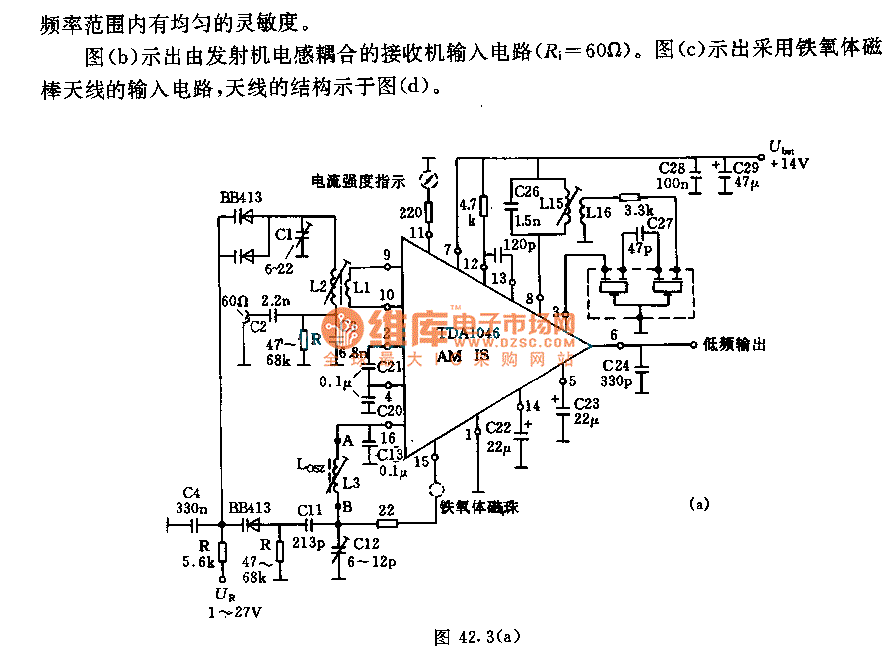
The receiver input circuit is designed to operate with a 60Ω generator, which ensures optimal impedance matching and efficient power transfer. The incorporation of a low-pass filter serves to eliminate high-frequency noise while allowing signals within the desired frequency range to pass through. This design choice is critical for maintaining uniform sensitivity across the operational bandwidth, thereby enhancing the overall performance of the receiver.
The coupling of the receiver's input circuit with the transmitter's inductive element is a key feature, as it facilitates the transfer of signals between the two components while maintaining the characteristic impedance of 60Ω. This coupling arrangement is essential for minimizing signal reflections and maximizing the efficiency of the system.
The use of a ferrite antenna in the input circuit provides several advantages, including improved signal reception and reduced interference. Ferrite antennas are known for their compact size and ability to operate effectively across a wide range of frequencies. The structural design of the ferrite antenna, as illustrated in the accompanying figure, is optimized to enhance its performance characteristics, such as gain and radiation pattern.
In summary, the receiver input circuit is a well-engineered assembly that integrates a 60Ω generator, a low-pass filter for frequency management, an inductive coupling mechanism with the transmitter, and a ferrite antenna for effective signal reception. Each component plays a crucial role in ensuring the reliable operation of the receiver within its intended application.The receiver ( Figure a) input circuit is supplied by the 60? generator. Low -pass filter allows the entire frequency range with uniform sensitivity. Figure b shows the receiver input circuit coupled with transmitter inductive (Ri = 60?). Figure c shows the input circuit with ferrite ferrite antenna, the antenna structure is shown in Figure (d).. 🔗 External reference
Related Circuits
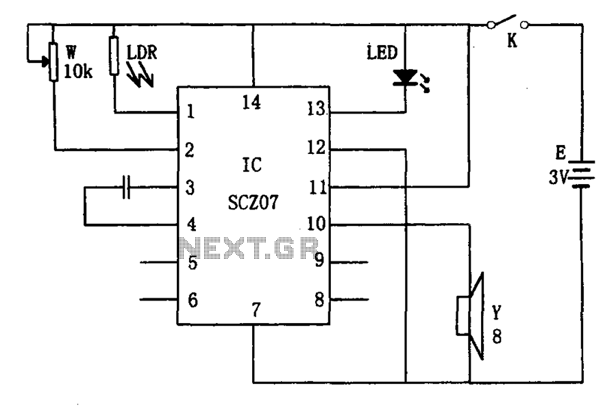
The weak light alarm circuit is illustrated in the figure. The oscillator circuit's core component is the SCZ07. The input signal is controlled by a potentiometer (W) and the output signal is processed by a photoresistor (LDR). The circuit...
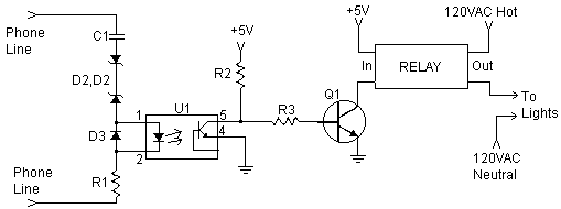
This document explains how to connect lights so that they flash when the phone rings. This setup is particularly beneficial in noisy environments, such as workshops, where it is challenging to hear the phone ringing. The ring detection component...
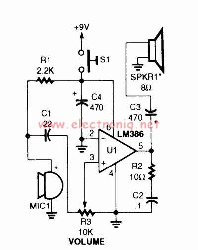
A voice amplifier can be designed using the LM386 power amplifier, which is intended for low voltage consumer applications. This simple circuit features variable gain and volume control. The gain is set internally to 20 to minimize the number...
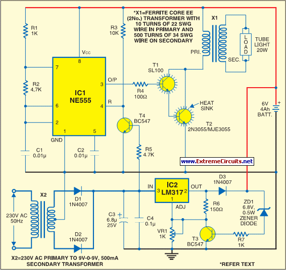
The circuit consists of inverter and charger sections. The inverter section utilizes the NE555 timer, while the charger section is based on the LM317 adjustable regulator. In the inverter section, the NE555 is configured as an astable multivibrator, generating...
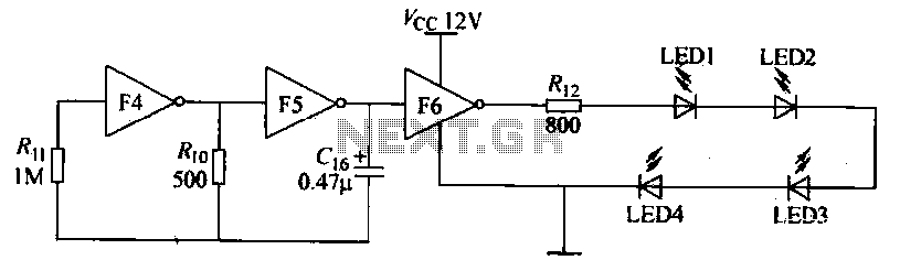
Gates F4, F5, and F6 together form a low-frequency oscillator that drives high-brightness light-emitting diode (LED) flashes. The light-emitting diodes may be arranged around the booth seat for decorative purposes. The automatic referral machine is used prior to operation...
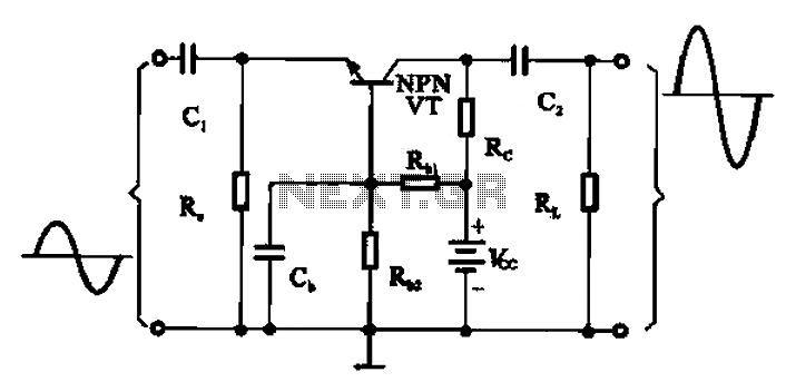
A common base transistor amplifier circuit is characterized by its basic structure, which includes key components such as a biasing resistor, capacitors for coupling, and an amplifying transistor. The circuit features four resistors that establish the quiescent point, with...