
IF AGO network circuit diagram
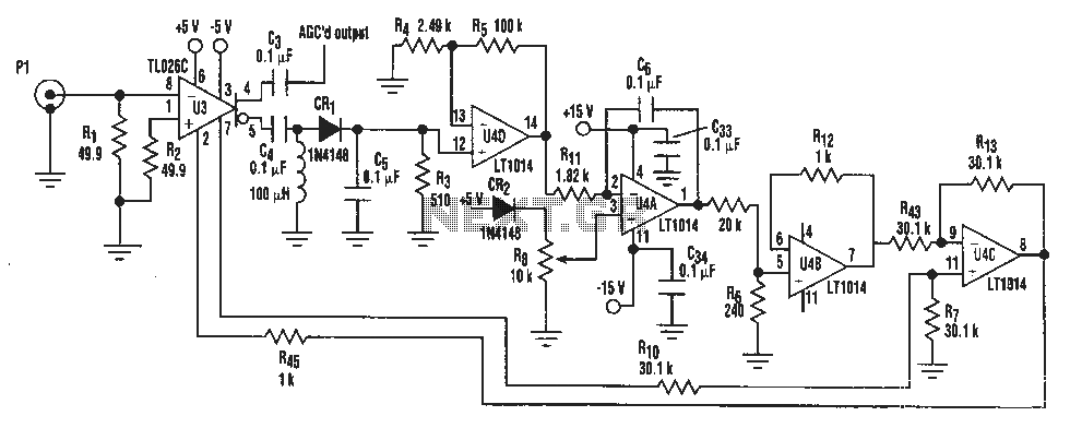
The described circuit utilizes the TL026C T1 voltage control amplifier, which is designed to provide gain control for intermediate frequency (IF) signals. This component is particularly advantageous in applications requiring automatic gain control (AGC) due to its ability to maintain a consistent output level across varying input signal amplitudes. The TL026C features low noise and high linearity, making it suitable for high-fidelity audio and RF applications.
In conjunction with the TL026C, the LT1014 quad op-amp can be employed to further process the signal. The LT1014 offers four independent, high-performance op-amps in a single package, allowing for versatile circuit configurations. Its characteristics include low offset voltage, low bias current, and high slew rate, contributing to overall system performance. This combination of components enables the design of a robust AGC circuit that can effectively handle a wide dynamic range of input signals while preserving signal integrity.
The overall schematic may include additional passive components such as resistors and capacitors to set the gain and filter the signal appropriately. By carefully selecting these components, the circuit designer can optimize the response time and stability of the AGC function, ensuring that it meets the specific requirements of the application. Proper layout and grounding techniques should also be employed to minimize noise and interference, enhancing the performance of the AGC system.A simple IF AGC signal over a wide dynamic range and excellent linearity characteristics, it may be composed of two chips to obtain: TL026C T1 voltage control amplifier IC and LT1014 (or any other similar basic quad op amp device ).
Related Circuits
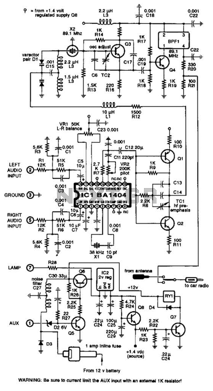
A BA1404 integrated circuit (IC) is utilized to generate a complete FM multiplex (MPX) signal. The chip incorporates all necessary circuitry. Components CI, R3, R4, and C4 are responsible for providing pre-emphasis. The transmitter operates on a single AA...
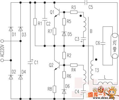
The saving lamp circuit features two main types: glass cover and exposed. The glass cover variants include three series: spherical, cylindrical, and processing types. The first two series consist of four variations: transparent, carved, engraved, and white. These lamps...
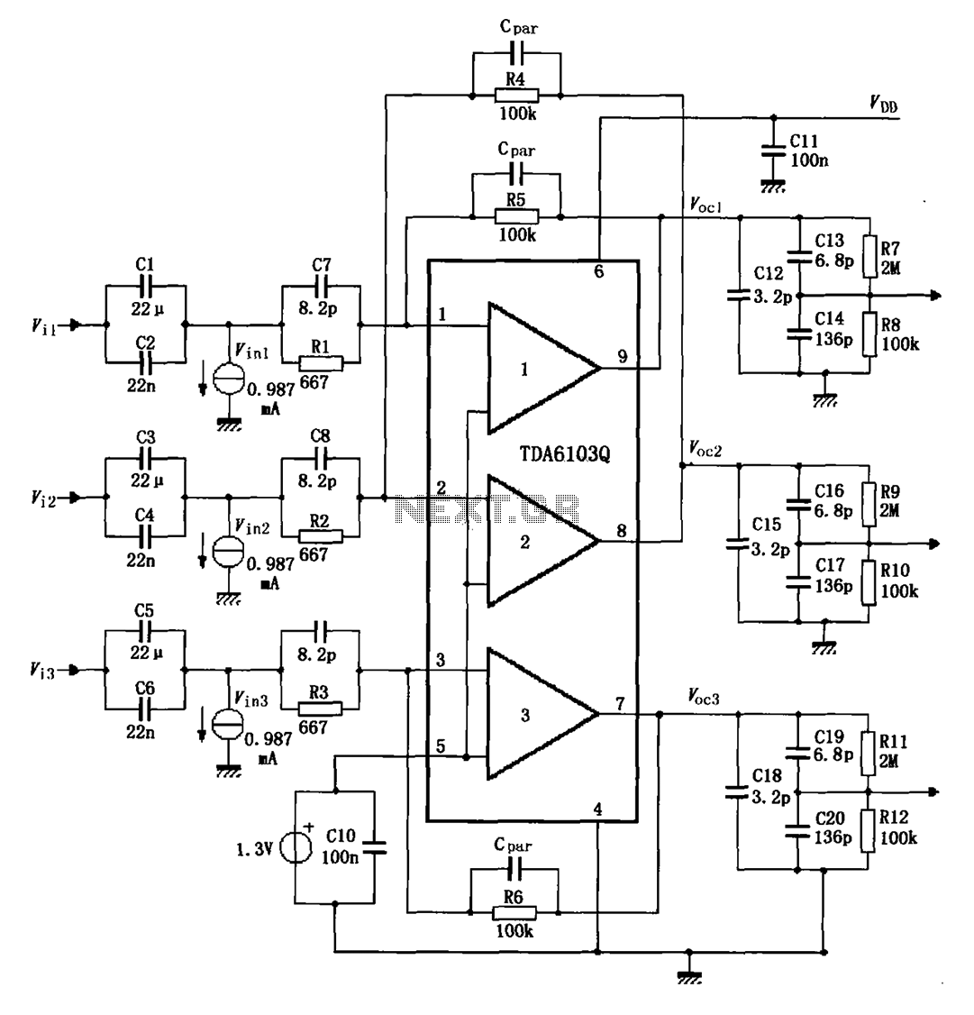
The TDA6103Q test circuit features a feedback factor of 1/150. Input signals Vi1, Vi2, and Vi3 are directed through an input resistor network that includes capacitors to the TDA6103Q pins 1, 2, and 3, which are part of the...
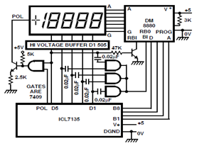
A circuit diagram for driving a plasma-type display using the ICL7135 is presented in the schematic. This application highlights the versatility of this integrated Analog to Digital Converter device. The ICL7135 is a high-precision, low-power, integrating Analog to Digital Converter...
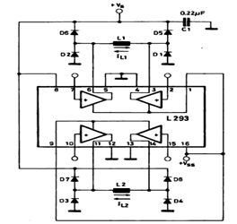
This circuit illustrates a basic configuration for driving a bipolar stepper motor using either an L293 or an L298N driver. It demonstrates that a single device can control a two-phase bipolar stepper motor. The circuit employs either the L293 or...

This small device can be aimed at a television to jam the remote control signal. The circuit design is straightforward. A 555 timer is configured as an astable multivibrator operating at a frequency of approximately 38 kHz, which is...