
Inductance adapter for frequency meter
This circuit is designed for measuring inductance by utilizing a Colpitts oscillator configuration. The oscillator consists of a combination of an inductor (LX) and capacitors (four 1000pF capacitors) that create a resonant frequency dependent on the inductance. The output of the oscillator is a sine wave that is subsequently amplified by a transistor stage. The second transistor amplifies the sine wave to ensure that it is strong enough for further processing.
Following amplification, the sine wave undergoes rectification through a diode-capacitor arrangement, converting the AC signal into a pulsating DC signal. This rectified signal, which now only contains positive voltage excursions, is then buffered by a third transistor to provide a stable output for the next stage.
The buffered signal is fed into a 74LS393 counter IC, which is configured to divide the frequency by 256. This division is crucial as it allows for easier measurement and interpretation of the frequency output. The output from pin 6 of the IC is then connected to a frequency meter, which displays the frequency corresponding to the inductance being measured.
Powering the circuit is a 9V battery, which supplies voltage to the 7805 voltage regulator, ensuring that the IC and transistors receive a stable 5V supply. The use of a high-frequency transistor, such as the 2SC9018, is essential due to the nature of the signal being processed; alternatives can be used if necessary, but they must meet the frequency requirements of the circuit.
Overall, this inductance measurement circuit is a practical implementation for measuring inductance values using frequency as a reference, allowing for precise calculations based on the output frequency displayed on the frequency meter.The following circuit enables me to measure inductance of the inductor labeled LX which is the inductance to be measured. The o/p of the circuit is a TTL square wave whose frequency relates to the inductance being measured.
The heart of the circuit is the buffer colpitts oscillator(the first stage) which resonates with the unknown inductance to give a Sine wave of a particular frequency. The frequency of the sine wave is a function of the unknown inductance and the four 1000pF capacitors.
The output sine wave is amplified by the second transistor and is then rectified by the capacitor and diode combination that Follows. The rectified sine wave now having only positive excursions is buffered by the third transistor and is then fed to the 74ls393 Counter ic which is configured as a divide by 256 counter.
The output of the ic pin 6 and ground is connected to the frequency meter. The inductance meter adapter output is connected to a frequency meter and the inductance is calculated from the frequency.Hence you need a frequency meter and some calculation to get your inductor value. All resistances are in ohms. 7805 positive regulator 5v o/p. 2SC9018 is a high frequency transistor with FT of 1.1 Ghz . you need high frequency transistors in the circuit where it is used in case you want to substitute for it.
I guess 2n2857, 2n5179 ,BF180 can be substituted. The 7805 regulator powers the IC and the last 2 transistors. The circuit operates from a 9V battery which also feeds the regulator. The Ic consists of two counters in one package of 14 pins hence you need just one. PIN 14 is VCC and PIN 7 is ground. The ic is TTl IC 🔗 External reference
Related Circuits
This project is exactly what you need. It is simple to construct and can be connected to almost any analogue multimeter. The scales are accurate over each range - certainly good enough to provide you with the value of...
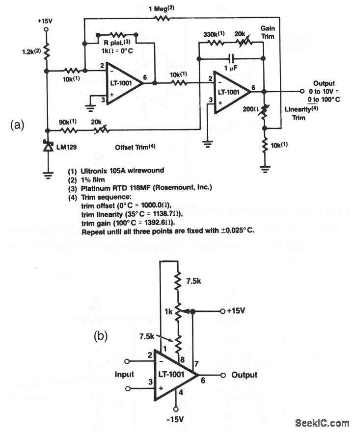
This circuit demonstrates an accuracy of ±0.025 °C across a temperature range of 0 °C to 100 °C, based on the specified values. The LT-1001's input offset voltage and its temperature drift are permanently calibrated to a low level...
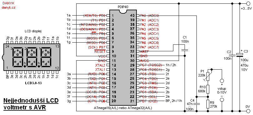
This is likely the simplest digital voltmeter utilizing an Atmel AVR microcontroller and an LCD display. The circuit is managed by a microprocessor IO1 - AVR Atmel ATmega16A, ATmega16L, ATmega16, ATmega32A, or ATmega32. A program is available for free...
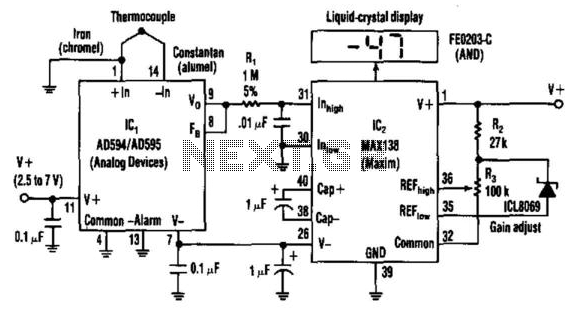
Using a J-type thermocouple, this circuit can indicate temperatures from -350° to 400° with a 6-V supply or from -50° to +100° with a 3-V lithium battery. The AD954 produces a 10 mV/°C output to the MAX 138 digital...
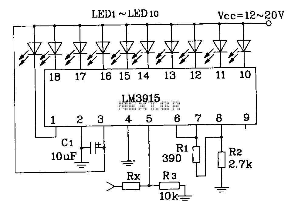
This document describes a simple LM3915 audio power meter circuit diagram. It notes that if the internal resistance of the speaker is 4 ohms, a resistor value of 10k ohms should be used for Rx. For an 8-ohm speaker,...
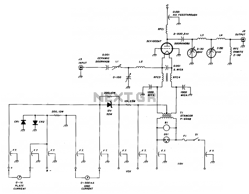
The amplifier utilizes a grounded grid circuit featuring either the Eimac 3CX1000A7 or 8877 ceramic/metal triodes designed for linear operation within the HF and VHF frequency ranges. It delivers a legal power output of 1500 watts PEP and continuous...
Warning: include(partials/cookie-banner.php): Failed to open stream: Permission denied in /var/www/html/nextgr/view-circuit.php on line 713
Warning: include(): Failed opening 'partials/cookie-banner.php' for inclusion (include_path='.:/usr/share/php') in /var/www/html/nextgr/view-circuit.php on line 713