
Inductivity Meter Using IC 555
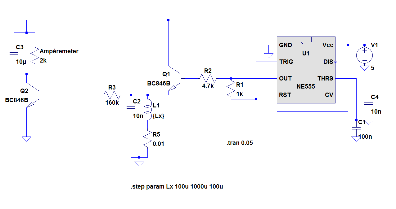
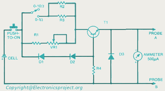
The inductance meter designed in this project utilizes the IC 555 timer in astable mode to generate a square wave signal. The frequency of this square wave is influenced by the inductance of the coil being measured, as well as the associated resistor and capacitor values in the circuit.
The basic configuration involves connecting the inductor in series with a known resistor and capacitor. The output frequency from the IC 555 is monitored, typically using a frequency counter or a microcontroller, which can translate the frequency into an inductance value based on the known values of the resistor and capacitor.
A transistor is employed in this circuit to amplify the output signal from the IC 555, ensuring that the frequency can be accurately measured even at low inductance values. The choice of transistor should be appropriate for the frequency range and the expected output load.
Resistors are used to set the timing characteristics of the IC 555, while capacitors are critical for determining the oscillation frequency. The design must ensure that the capacitor used has a suitable tolerance and temperature coefficient to maintain accuracy in measurements.
Overall, this inductance meter project serves as a practical application of basic electronics principles, demonstrating the use of common components to create a functional measuring device. The simplicity and low cost make it accessible for educational purposes and hobbyist experimentation.The aim of the project is to build simple low cost inductance meter. The main parts of the project are IC 555, Transistor, resistor and capacitor.. 🔗 External reference
Related Circuits
The circuit-delay relay for speakers serves as a delay mechanism that prevents the immediate activation of speakers when the amplifier is powered on. This feature is designed to protect the speakers from potential damage caused by sudden power surges....
This project measures the clock pulses supplied to the Timer input of the AVR microcontroller. The Bascom code counts the clock pulses over a duration of 1 second and displays the result. The circuit for this project primarily consists of...
Upon purchasing the slave dial, it arrived without instructions, packaging, or additional details. The only visible markings, aside from decades of grime, were on the face (SMITH SECTRIC, ACELEC SYDNEY) and some markings on the bracket holding the mechanism...
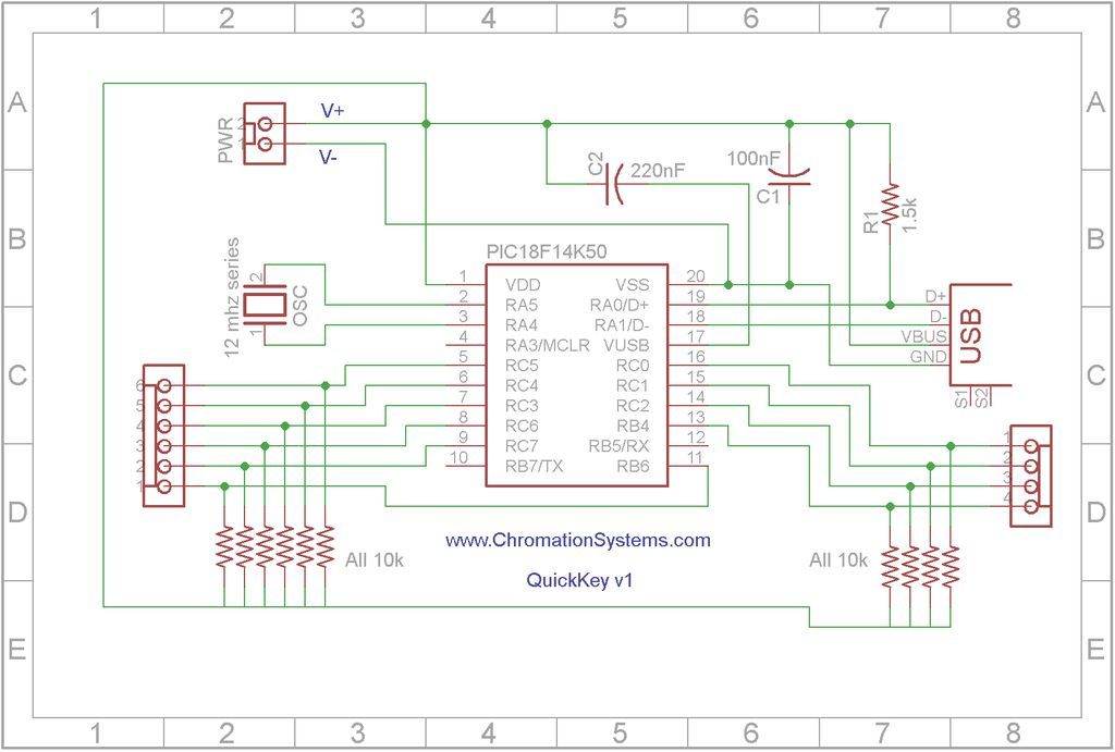
Quick Key Adapter, 10 Button HID Keyboard. This document outlines the process of creating a USB-connected Human Interface Device (HID) keyboard featuring 10 button inputs. The Quick Key Adapter is designed to facilitate user interaction through a compact keyboard interface....
This document provides a circuit diagram for an ohmmeter designed for low resistor measurements. Additional resources, including over 300 electronic circuits, are available on this site. The ohmmeter circuit is primarily used to measure the resistance of low-value resistors, typically...
For those who labvoeding built and flow of tension and a leader in providing circuit below was developed. If meter is a moving-coil meter 100?A useful. You have to make yourself a new scale. Also useful is a moving...
Warning: include(partials/cookie-banner.php): Failed to open stream: Permission denied in /var/www/html/nextgr/view-circuit.php on line 713
Warning: include(): Failed opening 'partials/cookie-banner.php' for inclusion (include_path='.:/usr/share/php') in /var/www/html/nextgr/view-circuit.php on line 713