Infrared Communication Systems
1. Principles of Infrared Transmission
Principles of Infrared Transmission
Electromagnetic Spectrum and Infrared Wavelengths
Infrared (IR) radiation occupies the electromagnetic spectrum between visible light and microwaves, with wavelengths ranging from 700 nm to 1 mm. For communication systems, the near-infrared (NIR) region (700–1400 nm) is most commonly used due to its compatibility with semiconductor materials like silicon and gallium arsenide. The energy of an IR photon is given by:
where h is Planck’s constant (6.626 × 10⁻³⁴ J·s), c is the speed of light (3 × 10⁸ m/s), and λ is the wavelength. At 850 nm, for example, the photon energy is approximately 1.46 eV.
Modulation Techniques
IR communication relies on modulating the intensity of the infrared beam to encode data. Common modulation schemes include:
- Pulse Position Modulation (PPM): Data is encoded in the temporal position of pulses within a fixed time frame.
- Amplitude Shift Keying (ASK): The amplitude of the IR carrier is varied to represent binary states.
- Frequency Shift Keying (FSK): The carrier frequency is shifted between discrete values.
The choice of modulation affects bandwidth efficiency and noise immunity. For instance, PPM offers better power efficiency but requires precise synchronization.
Link Budget Analysis
The performance of an IR communication link is governed by the link budget, which accounts for transmitted power, path loss, and receiver sensitivity. The received power Pr is derived from the Friis transmission equation:
where Pt is transmitted power, Gt and Gr are the gains of the transmitter and receiver antennas, and d is the distance between them. Atmospheric absorption and scattering further attenuate the signal, particularly in humid environments.
Noise Sources and Signal-to-Noise Ratio
Dominant noise sources in IR systems include:
- Shot noise: Arises from the quantum nature of light and is proportional to the square root of the photocurrent.
- Thermal noise: Generated by resistive components in the receiver circuit.
- Ambient light noise: Caused by sunlight or artificial lighting, which introduces unwanted photocurrent.
The signal-to-noise ratio (SNR) is critical for determining the bit error rate (BER) and is expressed as:
where R is the responsivity of the photodetector (A/W), q is the electron charge, Idark is the dark current, B is the bandwidth, k is Boltzmann’s constant, T is temperature, and RL is the load resistance.
Practical Considerations
IR communication systems face challenges such as:
- Line-of-sight requirements: IR beams cannot penetrate opaque obstacles, limiting non-directed configurations.
- Multipath dispersion: Reflections from surfaces cause intersymbol interference in indoor environments.
- Eye safety: High-power IR emitters must comply with IEC 60825 standards to avoid retinal damage.
Applications range from remote controls (using 940 nm LEDs) to high-speed free-space optical links (e.g., 1550 nm lasers for last-mile connectivity).
1.2 Infrared Spectrum and Wavelengths
The infrared (IR) spectrum occupies the electromagnetic region between visible light and microwaves, typically spanning wavelengths from 700 nanometers (nm) to 1 millimeter (mm). This range is subdivided into three primary bands based on atmospheric absorption characteristics and technological applications:
Near-Infrared (NIR)
Ranging from 700 nm to 1400 nm, NIR is closest to visible light and exhibits minimal atmospheric absorption. Its photon energy (E) can be calculated using Planck's relation:
where h is Planck's constant (6.626 × 10⁻³⁴ J·s), c is the speed of light (3 × 10⁸ m/s), and λ is the wavelength. For λ = 1000 nm:
Mid-Infrared (MIR)
Extending from 1400 nm to 3000 nm, MIR overlaps with the vibrational modes of many molecules, making it critical for spectroscopic applications. The Wien's displacement law relates peak emission wavelength (λmax) to blackbody temperature (T):
where b = 2.898 × 10⁻³ m·K. A human body at 310 K emits maximally at:
Far-Infrared (FIR)
Covering 3000 nm to 1 mm, FIR interacts strongly with rotational molecular states. The propagation loss (α) in dB/km through atmosphere follows the Beer-Lambert law:
where I0 and I are initial and transmitted intensities, and L is path length. Water vapor causes attenuation peaks at 2.7 μm, 6.3 μm, and 12-25 μm.
Atmospheric Transmission Windows
Three primary windows enable practical IR communication:
- 0.7-1.4 μm (Low-loss fiber optics)
- 3-5 μm (Thermal imaging)
- 8-14 μm (Remote sensing)
The transmittance (τ) through 1 km of standard atmosphere at sea level drops below 50% outside these windows due to H2O and CO2 absorption bands.
Material Interactions
The complex refractive index ñ = n + iκ governs IR behavior in materials, where n is the refractive index and κ the extinction coefficient. The penetration depth (δ) for intensity decay to 1/e is:
For silicon at λ = 1500 nm (κ ≈ 0.01), δ ≈ 12 μm, enabling photodetector design optimization.
1.3 Modulation Techniques in IR Communication
Fundamentals of Modulation in IR Systems
Infrared communication relies on modulating an optical carrier signal to encode information. Unlike RF systems, IR typically operates in the near-infrared spectrum (700 nm–1 mm), where intensity modulation is more practical than phase or frequency modulation due to detector characteristics. The baseband signal m(t) modulates the intensity of an IR LED or laser diode, producing the transmitted signal x(t):
where P0 is the average optical power, k is the modulation index (0 < k ≤ 1), and fc is the carrier frequency (typically 30–60 kHz for consumer IR). The receiver uses a photodiode with transimpedance amplification to convert the optical signal back to an electrical waveform.
Pulse Modulation Schemes
Three primary pulse-based modulation techniques dominate IR communication:
- Pulse-Width Modulation (PWM): Encodes information in the duration of pulses. Used in IR remote controls (e.g., NEC protocol), where a logical '1' might be a 1.125 ms pulse with 2.25 ms space, while '0' is a 1.125 ms pulse with 1.125 ms space.
- Pulse-Position Modulation (PPM): Encodes data in the temporal position of a pulse within a fixed time slot. Common in high-speed IR systems like IrDA, where the pulse shift represents multiple bits.
- Pulse-Code Modulation (PCM): Digitally samples the analog signal, converting it into a binary pulse sequence. Used in high-fidelity audio IR transmission.
Carrier-Based Modulation
For noise immunity, most IR systems employ subcarrier modulation, where the baseband signal modulates an intermediate frequency (IF) carrier before driving the LED:
Common subcarrier frequencies range from 36 kHz (TV remotes) to 455 kHz (high-speed data links). The receiver uses bandpass filtering centered at fsc to reject ambient light noise.
Amplitude Shift Keying (ASK)
The simplest digital modulation scheme, where:
Used in low-cost systems but susceptible to interference from fluorescent lights and sunlight.
Frequency Shift Keying (FSK)
Less common in IR due to detector limitations, but employed in some secure communication systems:
where Δf is the frequency deviation. Requires more complex receivers with frequency discrimination.
Advanced Techniques
For high-data-rate applications (>1 Mbps), quadrature amplitude modulation (QAM) and orthogonal frequency-division multiplexing (OFDM) are implemented in IR:
- QAM-IR: Combines amplitude and phase modulation, achieving spectral efficiencies up to 4 bits/symbol. Demonstrated in Li-Fi prototypes using resonant-cavity LEDs.
- OFDM-IR: Divides the spectrum into orthogonal subcarriers, mitigating multipath distortion in indoor environments. The IEEE 802.11bb standard specifies OFDM for light communications.
Practical Implementation Considerations
The choice of modulation involves trade-offs between:
- Power efficiency: PWM and PPM minimize average current draw
- Bandwidth: PCM and OFDM require wider bandwidth but support higher data rates
- Ambient light rejection: Subcarrier modulation provides 20–30 dB better noise immunity than baseband schemes
Modern IR transceivers (e.g., Vishay TFDU4101) integrate modulation/demodulation circuits, handling carrier generation and synchronization automatically.
2. Infrared Transmitters: LEDs and Laser Diodes
Infrared Transmitters: LEDs and Laser Diodes
Infrared Light-Emitting Diodes (IR LEDs)
Infrared LEDs are semiconductor devices that emit incoherent light in the 700 nm to 1 mm wavelength range when forward-biased. The spectral output is governed by the bandgap energy Eg of the semiconductor material, typically gallium arsenide (GaAs) or aluminum gallium arsenide (AlGaAs). The peak emission wavelength λp is given by:
where h is Planck's constant and c is the speed of light. For GaAs (Eg ≈ 1.42 eV), this yields λp ≈ 870 nm. The optical power output Po relates to the drive current IF as:
where ηe is the external quantum efficiency and e is the electron charge. Practical IR LEDs achieve radiant intensities of 10–100 mW/sr at 100 mA drive currents.
Infrared Laser Diodes
Laser diodes produce coherent, monochromatic light through stimulated emission in a Fabry-Pérot cavity. The threshold current density Jth for lasing is derived from the gain condition:
where Γ is the optical confinement factor, gth is the threshold gain, αi is the internal loss, L is the cavity length, and R1, R2 are facet reflectivities. Common infrared laser diodes use InGaAsP/InP heterostructures emitting at 1310 nm or 1550 nm for fiber-optic applications.
Modulation Characteristics
Both devices can be intensity-modulated for data transmission. The modulation bandwidth f3dB of LEDs is limited by carrier recombination:
where τr is the minority carrier lifetime (typically 1–10 ns, yielding 16–160 MHz bandwidth). Laser diodes exhibit relaxation oscillations with a resonance frequency:
where vg is the group velocity, a is the differential gain, ηi is the internal quantum efficiency, and Vp is the active layer volume.
Thermal Considerations
The wavelength temperature coefficient dλ/dT differs significantly between devices:
- LEDs: ~0.3 nm/K (due to bandgap shrinkage)
- Laser Diodes: ~0.1 nm/K (dominated by refractive index changes)
Thermal resistance Rth must be minimized to prevent thermal runaway in laser diodes, where the threshold current follows:
with T0 being the characteristic temperature (50–100 K for InGaAsP lasers).
Practical Implementation
Drive circuits require:
- LEDs: Constant current sources with fast switching (e.g., MOSFET-based drivers)
- Laser Diodes: Precision current sources with automatic power control (APC) loops
Optimal coupling efficiency is achieved through aspheric lenses (LEDs) or graded-index lenses (lasers) to match the emission patterns:
- LEDs: Lambertian emission profile (120° FWHM)
- Lasers: Elliptical Gaussian beam (5–10° × 20–40° FWHM)
2.2 Infrared Receivers: Photodiodes and Phototransistors
Photodiodes in Infrared Detection
Photodiodes are semiconductor devices that convert incident infrared (IR) radiation into an electrical current through the photoelectric effect. When photons with sufficient energy strike the diode’s depletion region, electron-hole pairs are generated, producing a photocurrent proportional to the incident optical power. The responsivity R of a photodiode is defined as:
where Ip is the photocurrent and Popt is the incident optical power. For typical silicon photodiodes in the near-IR range (700–1100 nm), R ranges from 0.5 to 0.7 A/W.
Key Performance Parameters
- Quantum Efficiency (η): The ratio of generated electrons to incident photons, given by:
where h is Planck’s constant, c is the speed of light, e is the electron charge, and λ is the wavelength.
- Dark Current: Leakage current in the absence of light, critical for low-light applications.
- Response Time: Determined by the junction capacitance and carrier transit time, often in the nanosecond range for high-speed IR communication.
Phototransistors for Enhanced Sensitivity
Phototransistors amplify the photocurrent by leveraging the transistor’s current gain (β). Unlike photodiodes, they operate in active mode, with the base current generated by photon absorption. The collector current IC is:
This makes phototransistors suitable for low-intensity IR signals but at the cost of slower response times (microseconds) due to charge storage effects.
Trade-offs Between Photodiodes and Phototransistors
- Photodiodes: Faster, linear response, but require external amplification.
- Phototransistors: Higher sensitivity, but slower and prone to saturation.
Practical Considerations in Receiver Design
To minimize noise in IR receivers:
- Use a transimpedance amplifier (TIA) for photodiodes to convert current to voltage while maintaining bandwidth.
- Implement optical bandpass filters to reject ambient light interference.
- For phototransistors, bias the collector-emitter voltage (VCE) to avoid saturation.
Applications in Modern Systems
Photodiodes dominate high-speed IR communication (e.g., fiber optics, LiDAR), while phototransistors are preferred in proximity sensors and remote controls due to their integrated gain. Emerging technologies like quantum dot photodiodes are pushing detectivity limits beyond traditional InGaAs systems.
2.3 Signal Conditioning Circuits
Signal conditioning circuits are critical in infrared (IR) communication systems to ensure optimal signal integrity, noise immunity, and compatibility with subsequent processing stages. These circuits typically include amplification, filtering, and modulation/demodulation stages to enhance the weak IR signals received by photodiodes or phototransistors.
Amplification and Transimpedance Design
The primary challenge in IR signal conditioning is amplifying the weak photocurrent generated by the detector while minimizing noise. A transimpedance amplifier (TIA) is commonly employed, converting the photodiode current into a voltage signal. The feedback resistor Rf and capacitor Cf determine the gain and bandwidth:
where Iph is the photodiode current. The bandwidth is constrained by the amplifier's gain-bandwidth product (GBWP) and the photodiode capacitance Cd:
To minimize noise, a low-noise operational amplifier (e.g., JFET-input) and careful PCB layout techniques (e.g., guarding, shielding) are essential.
Bandpass Filtering for Noise Reduction
IR communication systems often operate in environments with ambient IR interference (e.g., sunlight, incandescent lighting). A bandpass filter centered at the carrier frequency (typically 38 kHz for consumer IR) suppresses out-of-band noise. A multiple feedback (MFB) bandpass filter provides a sharp roll-off:
where f0 is the center frequency and Q is the quality factor. Higher Q improves selectivity but reduces bandwidth.
Demodulation and Threshold Detection
For pulse-modulated IR signals (e.g., RC-5, NEC protocols), an envelope detector followed by a comparator extracts the digital signal. The comparator's hysteresis prevents noise-induced false triggering:
where Vth is the threshold voltage. A Schmitt trigger configuration ensures clean digital output even with noisy input.
Practical Implementation Considerations
- Power supply decoupling: Bypass capacitors (e.g., 100 nF ceramic + 10 μF electrolytic) minimize supply noise.
- Component selection: Low-tolerance resistors (1%) and NP0/C0G capacitors ensure stable filter characteristics.
- Layout techniques: Short traces, ground planes, and proper photodiode biasing reduce parasitic effects.
3. Common IR Protocols: RC5, NEC, and SIRC
3.1 Common IR Protocols: RC5, NEC, and SIRC
RC5 Protocol
The RC5 protocol, developed by Philips, is a widely used infrared communication standard for remote control applications. It employs Manchester encoding to ensure robust data transmission with a carrier frequency of 36 kHz. Each RC5 frame consists of 14 bits:
- 2 start bits (always logic '1')
- 1 toggle bit (increments with each keypress)
- 5 address bits (device identifier)
- 6 command bits (function code)
The bit duration is standardized at 1.778 ms, resulting in a total frame time of 25 ms. The Manchester encoding scheme ensures synchronization by representing logic '1' as a high-to-low transition and logic '0' as a low-to-high transition at the midpoint of the bit period.
NEC Protocol
The NEC protocol is another prevalent IR standard, characterized by its pulse distance modulation. It uses a 38 kHz carrier and encodes data with pulse bursts of varying lengths. A complete NEC frame comprises:
- 9 ms leading pulse burst (start marker)
- 4.5 ms space
- 8-bit address (LSB first)
- 8-bit command (LSB first)
- 8-bit inverted address (error checking)
- 8-bit inverted command (error checking)
- 562.5 µs stop pulse
Logical '0' is represented by a 562.5 µs pulse followed by a 562.5 µs space, while logical '1' consists of a 562.5 µs pulse followed by a 1.6875 ms space. The protocol's redundancy in transmitting inverted address and command bytes enhances reliability.
Sony SIRC Protocol
The Sony SIRC (Serial Infrared Remote Control) protocol is a simpler yet efficient standard with variable command lengths (12, 15, or 20 bits). It operates at a carrier frequency of 40 kHz and uses pulse width encoding:
- 12-bit variant: 7 command bits + 5 address bits
- 15-bit variant: 7 command bits + 8 address bits
- 20-bit variant: 7 command bits + 5 address bits + 8 extended bits
Each bit begins with a 600 µs pulse burst. A logical '1' is followed by a 1.2 ms space, while a logical '0' is followed by a 600 µs space. The total frame time depends on the number of '1's and '0's transmitted, making SIRC less deterministic than RC5 or NEC.
Comparative Analysis
The three protocols differ in modulation techniques, error handling, and efficiency:
- RC5: Manchester encoding ensures synchronization but requires precise timing.
- NEC: Pulse distance modulation with redundancy improves noise immunity.
- SIRC: Simpler encoding but lacks built-in error checking.
In practice, NEC is favored for consumer electronics due to its balance of robustness and simplicity, while RC5 remains prevalent in professional systems requiring toggle bit functionality.
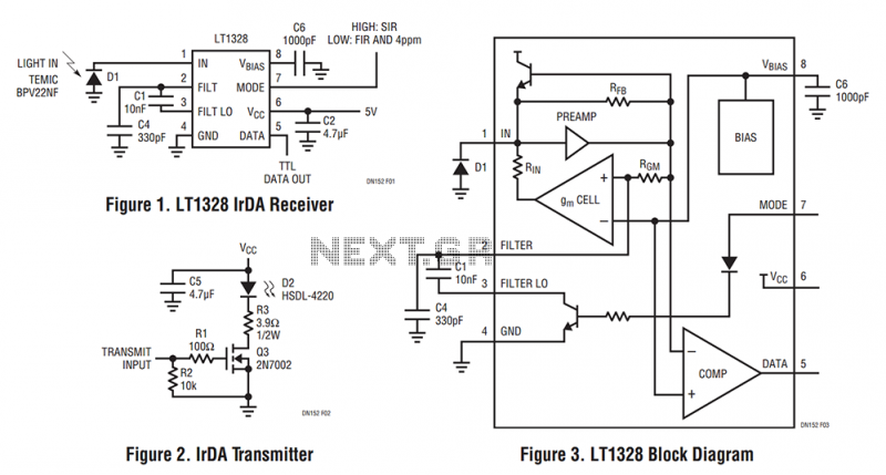
3.2 IR Data Association (IrDA) Standards
The Infrared Data Association (IrDA) standards define a suite of protocols for short-range, line-of-sight infrared communication. Developed in the 1990s, these standards enable reliable data exchange between devices such as laptops, PDAs, printers, and mobile phones. IrDA operates in the near-infrared spectrum (850–900 nm), leveraging pulse-position modulation (PPM) and asynchronous serial communication.
Physical Layer Specifications
IrDA defines multiple physical layer (PHY) standards, each optimized for specific data rates and power constraints:
- IrDA-SIR (Serial Infrared): Supports data rates up to 115.2 kbps using asynchronous UART communication with 3/16 pulse modulation.
- IrDA-MIR (Medium Infrared): Achieves 0.576–1.152 Mbps with 4-PPM encoding.
- IrDA-FIR (Fast Infrared): Delivers 4 Mbps using amplitude shift keying (ASK) with a 500 ns pulse width.
- IrDA-VFIR (Very Fast Infrared): Extends speeds to 16 Mbps via Hole-Accumulation Diode (HAD) photodetectors.
The transmission range is typically limited to 1 meter, with a half-angle divergence of 15–30 degrees to minimize interference. The link budget is governed by the inverse-square law:
where \(P_r\) is received power, \(P_t\) is transmitted power, \(\lambda\) is wavelength, \(d\) is distance, and \(\eta_t, \eta_r\) are transmitter/receiver efficiencies.
Protocol Stack Architecture
IrDA's layered protocol stack includes:
- IrPHY (Physical Layer): Handles modulation, encoding, and optical characteristics.
- IrLAP (Link Access Protocol): Manages device discovery, connection establishment, and error control via HDLC framing.
- IrLMP (Link Management Protocol): Multiplexes multiple logical channels over a single IrLAP connection.
- IrCOMM/IrOBEX (Application Protocols): Emulate serial ports (IrCOMM) or facilitate object exchange (IrOBEX).
Devices negotiate parameters during the Discovery Phase using a 500 ms sniff interval and 8–10 discovery slots. The Normal Connect Phase employs a 1.6 μs guard time between bytes to prevent overlap.
Error Handling and Performance
IrDA uses CRC-16 for error detection and selective repeat ARQ for retransmission. The bit error rate (BER) is approximated by:
where \(E_b/N_0\) is the energy-per-bit-to-noise ratio. Typical implementations achieve a BER of \(10^{-9}\) at 1 meter.
Modern Applications and Limitations
Despite being supplanted by Bluetooth and Wi-Fi, IrDA remains relevant in:
- Medical devices (immune to RF interference).
- Industrial control systems (secure, short-range links).
- Legacy POS terminals (simple, low-cost implementation).
Key limitations include susceptibility to ambient light noise and strict alignment requirements. Recent advancements like IrDA Control optimize the standard for low-power remote control applications.
3.3 Error Detection and Correction Methods
Infrared communication systems are susceptible to noise, interference, and signal degradation, necessitating robust error detection and correction techniques. These methods ensure data integrity by identifying and rectifying bit errors introduced during transmission.
Parity Check
The simplest form of error detection is the parity check, where an additional bit (parity bit) is appended to a data word to ensure an even or odd number of set bits. For a data word D of length n, the parity bit P is computed as:
If a single-bit error occurs, the receiver detects a parity mismatch. However, this method fails for even-numbered bit errors and does not correct errors.
Checksum
A checksum extends the parity concept by summing all data words and transmitting the result. The receiver recomputes the checksum and compares it with the received value. While computationally efficient, checksums are vulnerable to certain error patterns, such as reordered data words.
Cyclic Redundancy Check (CRC)
CRC is a more robust error-detection method using polynomial division. The sender appends a checksum (remainder) derived from dividing the data by a predefined generator polynomial G(x). The receiver performs the same division; a non-zero remainder indicates errors.
Common CRC polynomials include CRC-16 (x16 + x15 + x2 + 1) and CRC-32, used in Ethernet and ZIP files.
Hamming Codes
Hamming codes enable single-bit error correction and double-bit error detection. For a data word of length k, r parity bits are added such that 2r ≥ k + r + 1. The parity bits are placed at positions that are powers of two (1, 2, 4, etc.), and each covers a specific subset of data bits.
The syndrome identifies the erroneous bit position, allowing correction.
Reed-Solomon Codes
For burst errors common in infrared channels, Reed-Solomon (RS) codes are highly effective. RS codes operate on symbols rather than bits, correcting up to t symbol errors where t = (n - k)/2. They are widely used in optical communications, QR codes, and CDs.
where m is the symbol size in bits.
Automatic Repeat Request (ARQ)
ARQ protocols, such as Stop-and-Wait or Selective Repeat, combine error detection with retransmission requests. The receiver sends an acknowledgment (ACK) for correct frames or a negative acknowledgment (NACK) for corrupted ones, prompting retransmission. ARQ is efficient in low-noise environments but introduces latency.
Forward Error Correction (FEC)
FEC integrates error correction directly into the transmitted data, eliminating the need for retransmissions. Convolutional codes and Turbo codes are advanced FEC techniques used in deep-space communications and 4G/5G networks. The Viterbi algorithm decodes convolutional codes by finding the most likely transmitted sequence.
where k is the number of information bits and n is the total encoded bits.
4. Remote Control Systems
4.1 Remote Control Systems
Fundamentals of Infrared Remote Control
Infrared (IR) remote control systems operate by modulating near-infrared light (typically 850–950 nm) to transmit digital commands. The carrier frequency, usually between 36 kHz and 56 kHz, is chosen to minimize interference from ambient light sources. The modulation scheme is typically pulse-width modulation (PWM) or pulse-distance modulation (PDM), with Manchester or RC-5 encoding for robustness.
where PIR is the emitted IR power, P0 is the LED's peak power, ηLED is the electro-optical conversion efficiency, and D is the duty cycle of the modulation.
Signal Encoding Protocols
Common IR protocols include:
- NEC Protocol: Uses 38 kHz carrier, 16-bit address and command fields, with pulse-distance encoding.
- RC-5: 36 kHz carrier, 14-bit frames with Manchester coding for DC balance.
- SIRC (Sony): 40 kHz carrier, 12–20 bit frames with PDM for extended range.
The bit duration Tb is derived from the carrier period Tc and the encoding scheme. For NEC:
where Ncycles is the number of carrier cycles per bit (e.g., 16 for logical '0' in NEC).
Receiver Design and Noise Immunity
IR receivers integrate a photodiode, transimpedance amplifier, bandpass filter (centered at the carrier frequency), and demodulator. The signal-to-noise ratio (SNR) is critical:
where R is the photodiode responsivity (A/W), Idark is the dark current, Ibg is background light current, and B is the bandwidth.
Practical Implementation Challenges
Key design considerations include:
- Line-of-sight limitations: Diffuse reflection or repeater systems mitigate obstructions.
- Power consumption: Low-duty-cycle transmission and sleep modes extend battery life.
- Interference: Synchronous protocols (e.g., RC-6) reduce collisions in multi-device environments.
Advanced Applications
Modern systems incorporate bidirectional IR (e.g., HDMI-CEC) or hybrid RF/IR solutions for extended range. Machine learning is increasingly used for gesture recognition via IR array sensors.
4.2 Short-Range Data Transfer
Operating Principles
Short-range infrared (IR) data transfer relies on modulated near-infrared light (700–1000 nm) for communication over distances typically less than 1 meter. The transmitter encodes data by varying the intensity of an IR LED, while the receiver decodes the signal using a photodiode or phototransistor. The system operates in one of two modes:
- Directed (line-of-sight): Requires precise alignment between transmitter and receiver, achieving higher data rates (up to 4 Mbps in IrDA protocols).
- Diffuse (non-line-of-sight): Uses reflected IR signals, sacrificing bandwidth (typically < 115 kbps) for flexibility in device positioning.
Modulation Techniques
To mitigate ambient IR noise, pulse modulation schemes are employed:
where P0 is the baseline optical power, m the modulation index (0.7–0.9 for typical systems), s(t) the data signal, and fc the carrier frequency (typically 30–56 kHz for consumer electronics). Common protocols include:
- IrDA SIR: Uses asynchronous UART framing with 3/16 pulse encoding (1.6 μs pulses for '1', no pulse for '0')
- IrDA FIR: Implements 4-PPM (Pulse Position Modulation) for 4 Mbps operation
Channel Characteristics
The path loss in IR systems follows an inverse-square law with additional atmospheric attenuation:
where Ar is the receiver area, d the distance, θ the beam divergence angle, and α the atmospheric attenuation coefficient (~0.1 dB/m in clear air). Multipath dispersion in diffuse systems causes intersymbol interference (ISI), limiting the maximum symbol rate to:
with τrms being the RMS delay spread of the channel.
Practical Implementations
Modern IR transceivers integrate automatic gain control (AGC) and adaptive equalization to combat channel impairments. The IrPHY standard specifies:
- Minimum irradiance of 4 mW/sr for transmitters
- Receiver sensitivity better than 4 μW/cm²
- Half-angle beam divergence of ±15°
Typical applications include:
- Contactless payment systems (ISO/IEC 15693)
- Medical device synchronization (IEEE 11073-20601)
- Industrial control networks with EMI immunity requirements
Error Performance Analysis
The bit error rate (BER) for an OOK-modulated IR link under shot noise follows:
where η is the detector quantum efficiency, Ps the signal power, hν the photon energy, B the bandwidth, Pb the background radiation power, and Pdc the dark current power. Forward error correction (FEC) codes like Reed-Solomon (255,223) are commonly applied to achieve BER < 10⁻⁹ in commercial systems.
4.3 Industrial and Medical Applications
Industrial Automation and Control
Infrared (IR) communication systems are extensively deployed in industrial environments for wireless data transmission between sensors, actuators, and control units. Unlike radio-frequency (RF) systems, IR avoids electromagnetic interference (EMI) with sensitive industrial equipment. The line-of-sight requirement is often mitigated by using diffuse IR configurations, where signals reflect off surfaces to reach receivers.
Here, \(P_r\) is received power, \(P_t\) is transmitted power, \(\lambda\) is wavelength, \(d\) is distance, \(G_t\) and \(G_r\) are antenna gains, and \(\eta_{\text{atm}}\) and \(\eta_{\text{opt}}\) account for atmospheric and optical losses. Industrial IR links typically operate at 850–950 nm for optimal penetration through dust and vapors.
Medical Telemetry and Diagnostics
In medical applications, IR enables non-invasive patient monitoring through pulse oximeters, capnographs, and implantable device telemetry. Near-infrared (NIR) spectroscopy (700–2500 nm) exploits tissue transparency to measure blood oxygenation (\(SpO_2\)) via the Beer-Lambert law:
where \(I\) is transmitted intensity, \(I_0\) is incident intensity, \(\epsilon\) is molar absorptivity, \(c\) is concentration, and \(l\) is path length. IR-based endoscopic capsules transmit real-time imagery at 20–50 Mbps using on-off keying (OOK) modulation.
Case Study: IR in Sterile Environments
Pharmaceutical cleanrooms employ IR data links to maintain sterility by eliminating cable ports. A 2021 study demonstrated a 10-meter IR network achieving 1 Gbps via vertical-cavity surface-emitting lasers (VCSELs) and avalanche photodiodes (APDs), with bit-error rates (BER) below \(10^{-12}\).
Safety and Regulatory Compliance
Industrial IR systems must comply with IEC 62471 for photobiological safety, limiting irradiance to 10 W/m² for prolonged exposure. Medical devices adhere to FDA 21 CFR 1040.10, requiring fail-safe beam termination at >5 mW output.
Modern implementations integrate adaptive optics to compensate for misalignment in vibrating machinery, using MEMS-based beam steering with <1 ms latency.
5. Range and Line-of-Sight Requirements
5.1 Range and Line-of-Sight Requirements
Infrared (IR) communication systems rely on the propagation of electromagnetic waves in the 700 nm to 1 mm wavelength range, typically operating between 300 GHz and 430 THz. The effective range of such systems is governed by the inverse square law, atmospheric absorption, and the necessity for an unobstructed line-of-sight (LOS) path.
Power Budget and Range Limitations
The maximum achievable range d of an IR communication link is determined by the transmitted power Pt, receiver sensitivity Pr, and the system's optical efficiency. The Friis transmission equation for free-space optical communication is given by:
where:
- Gt and Gr are the transmitter and receiver antenna gains,
- λ is the wavelength,
- ηt and ηr are the optical efficiencies of the transmitter and receiver, respectively.
Atmospheric attenuation further reduces the received power due to scattering and absorption by molecules such as H2O and CO2. The Beer-Lambert law describes this attenuation:
where α is the attenuation coefficient, which varies with wavelength and environmental conditions.
Line-of-Sight (LOS) Constraints
Unlike radio-frequency (RF) systems, IR communication requires a direct, unobstructed path between transmitter and receiver. Diffraction effects are negligible due to the short wavelength, making non-LOS (NLOS) communication impractical without reflectors or repeaters. The divergence angle θ of the IR beam influences the required alignment precision:
where w0 is the beam waist radius. Narrow beams enable longer ranges but demand precise pointing mechanisms.
Practical Considerations
In real-world deployments, IR communication systems face challenges such as:
- Ambient IR noise from sunlight and artificial lighting, which increases the bit error rate (BER).
- Beam misalignment due to mechanical vibrations or thermal expansion.
- Weather conditions like fog or rain, which scatter IR radiation.
Advanced modulation techniques (e.g., pulse-position modulation) and error-correcting codes are often employed to mitigate these issues.
Case Study: IRDA Standard
The Infrared Data Association (IrDA) specifies short-range (< 1 m) communication with a half-angle divergence of 15°–30°. This trade-off between range and alignment tolerance makes IrDA suitable for portable devices like smartphones and laptops.
5.2 Ambient Light Interference and Mitigation
Infrared (IR) communication systems are susceptible to ambient light interference, which introduces noise and reduces signal integrity. This interference arises from natural and artificial sources, including sunlight, incandescent bulbs, and fluorescent lighting, all of which emit IR radiation overlapping with the communication band.
Sources of Ambient Light Interference
The primary contributors to ambient IR noise are:
- Sunlight – Contains significant IR components, particularly in the near-infrared (NIR) range (700–1100 nm).
- Incandescent bulbs – Emit broadband IR radiation peaking around 1000 nm due to blackbody radiation.
- Fluorescent/LED lighting – While more spectrally confined, some emissions fall within the IR communication bands.
The spectral irradiance of these sources can be modeled using Planck's law for thermal emitters and empirical data for artificial lighting.
Quantifying Interference: Signal-to-Noise Ratio (SNR)
The SNR in an IR communication link is given by:
where:
- S(λ) is the spectral power density of the signal,
- N(λ) is the spectral noise power density from ambient sources,
- λ1 and λ2 define the communication bandwidth.
Mitigation Techniques
1. Optical Filtering
Bandpass optical filters attenuate out-of-band noise while transmitting the desired IR signal. The filter's transmission coefficient T(λ) modifies the SNR as:
Common filter types include:
- Interference filters – Narrowband (FWHM ≈ 10–50 nm), high out-of-band rejection.
- Absorptive filters – Broader but immune to angle-dependent wavelength shifts.
2. Modulation Techniques
High-frequency modulation (e.g., 38–56 kHz) shifts the signal beyond the flicker noise of ambient sources. The receiver uses synchronous detection to reject low-frequency noise:
where s(t) is the received signal and carrier(t) is the reference waveform.
3. Adaptive Thresholding
Real-time adjustment of the detection threshold compensates for varying ambient conditions. A feedback loop measures the DC offset from ambient light and subtracts it:
where α and β are empirically determined constants.
Case Study: Sunlight-Resistant IR Receiver
A high-performance design might combine:
- A 950 nm bandpass filter (FWHM = 40 nm),
- 38 kHz carrier modulation,
- Automatic gain control (AGC) with a dynamic range > 80 dB.
Laboratory tests show such systems achieve BER < 10−6 under direct sunlight (100 klux).
Practical Considerations
In industrial settings, flickering from high-intensity discharge (HID) lamps requires additional notch filtering at harmonics of the mains frequency (50/60 Hz and multiples).
5.3 Power Consumption and Efficiency
Power Dissipation in IR Transmitters
The dominant source of power consumption in infrared (IR) communication systems is the transmitter, primarily due to the forward current required to drive the IR LED. The instantaneous power dissipation Pdiss in an IR LED is given by:
where Vf is the forward voltage drop (typically 1.2–1.6 V for GaAs LEDs) and If is the forward current. For pulsed operation, the average power Pavg must account for the duty cycle D:
High-speed communication often demands short, high-current pulses (e.g., 50–100 mA) with low duty cycles (1–10%), reducing average power but requiring careful thermal management.
Modulation Efficiency
Efficiency in IR systems is heavily influenced by the modulation scheme. On-off keying (OOK), the most common method, has a theoretical power efficiency ηmod of:
where Ppeak is the peak optical power. For example, a 38 kHz carrier modulated at 50% duty cycle with a 100 mA pulse achieves ~40% efficiency, while subcarrier modulation (e.g., PWM or PPM) can improve this to 60–70% by optimizing pulse positioning.
Receiver Sensitivity and Power Trade-offs
The minimum detectable power Pmin at the receiver is governed by the photodiode's responsivity R (A/W) and noise equivalent power (NEP):
where Id is the dark current and Δf is the bandwidth. To minimize transmitter power, receivers often employ transimpedance amplifiers (TIAs) with high gain (>1 MΩ) and low input-referred noise (<1 pA/√Hz).
Thermal Constraints
Junction temperature rise in IR LEDs follows:
where Rth is the thermal resistance (typically 50–200 °C/W for SMD LEDs). Exceeding the maximum junction temperature (often 85–125°C) degrades output power and lifetime. Heat sinks or pulsed operation mitigate this.
Case Study: Remote Control Optimization
In TV remotes, a 940 nm LED driven at 50 mA (1.4 V) with 5% duty cycle consumes:
Modern designs achieve < 1 mW average power by using adaptive pulse-width modulation and sleep modes between transmissions.
6. Key Research Papers and Articles
6.1 Key Research Papers and Articles
- Design and deployment of IoT based underwater wireless communication ... — Visible Light Communication (VLC) is an alternative method to the standard communication systems such as radio frequency (RF) and acoustic systems and also has brought more attention by researchers [10].The main reasons are one, the improvement of low-cost light-emitting diodes (LEDs) and second the desire to have high-speed real-time communication devices for high speed applications.
- A hybrid power line and visible light communication system for indoor ... — His research interests lie in the field of channel estimation and equalization for multimedia communication systems as well as the power line communication and visible light communication. Fang Yang received his BSE and PhD degree in 2005 and 2009, respectively, from the Department of Electronic Engineering in Tsinghua University, Beijing, China.
- Infrared wireless communication system - Academia.edu — The paper presents an overview of infrared wireless communication systems, highlighting their basic principles, operational contexts, and key applications. It emphasizes the advantages and limitations of using infrared technology for wireless communication, particularly its dependence on line-of-sight and environmental factors affecting signal ...
- Infrared: A Key Technology for Security Systems - Corsi - 2012 ... — These programs included experimental systems for enemy intrusion/detection, remote temperature sensing, secure communications, and "flying torpedo" guidance. An infrared search system tested during this period was able to detect an approaching airplane at a distance of 1.5 km, or a person more than 300 meters away.
- Infrared Technology and Applications XLI | (2015) - SPIE — It is focused on a 360° close day/night surveillance system around the ship to detect and track these specific threats. The observation module presented hereafter takes advantage of Sagem experience in naval applications and infrared-based surveillance systems. The paper puts forward the detection process (image processing and 3D tracking).
- Development and Core Technologies for Intelligent SWaP3 Infrared ... — In addition to the two core means of optical and electronic systems mentioned above, the optimization of a power management system is also useful to achieve lightweight and integration. By adopting a new highly integrated power management system and equipping it with microprocessors, intelligent management, and rational layout can be realized.
- Systems Analysis for Thermal Infrared ' THz Torch - Springer — The 'THz Torch' concept was recently introduced by the authors for providing secure wireless communications over short distances within the thermal infrared (10-100 THz). Unlike conventional systems, thermal infrared can exploit front-end thermodynamics with engineered blackbody radiation. For the first time, a detailed power link budget analysis is given for this new form of wireless link ...
- PDF MIT Open Access Articles — consider it timely to launch a second feature issue dedicated to mid-infrared optical materials and their device applications. The 22 papers in this feature issue can be roughly divided into six topical areas: 1) mid-IR laser materials and sources; 2) materials and strategies for infrared detection; 3) narrow-gap
- PDF Ir Wireless Underwater Communication System - Irjet — (NIR), So the used part of the infrared spectrum in laser communication system is divided into various bands based on the type of the light sources, transmitting\absorbing materials (fibres) and detectors. IR communication system consists of three main parts transmitter circuit, medium propagation (IR) and receiver circuit.
- An Infrared Network for Mobile Computers - ResearchGate — Ethernet communication has much lower latenc y than tab infrared communication. 5.2 T ab-T o-Application Events The tab transmits button and pen ev ents as IR packets.
6.2 Recommended Books on IR Communication
- PDF Fundamentals of Electro-Optic Systems Design Communications, Lidar, and ... — 11 Communications in the optical scatter channel 249 11.1 Introduction 249 11.2 Optical scatter channel models 249 11.3 Analytical models and relationships for optical propagation in the ocean 254 11.4. System design models for the optical scatter channel 263 11.5 Over the horizon optical communications 277 A Two-dimensional Poisson processes 283
- PDF Ir Wireless Underwater Communication System - Irjet — (NIR), So the used part of the infrared spectrum in laser communication system is divided into various bands based on the type of the light sources, transmitting\absorbing materials (fibres) and detectors. IR communication system consists of three main parts transmitter circuit, medium propagation (IR) and receiver circuit.
- Infrared wireless communication system - Academia.edu — Infrared systems have already proven their effectiveness for short-range temporary communications and in high data rate longer range point-to-point systems TABLE 6.1 Infrared Versus Other Communication Method Signal Cable electrical signal optical signal Wireless electromagnetic wave radio (≤3THz) infrared beam Media copper cable optical ...
- The Infrared & Electro-Optical Systems Handbook. Electro-Optical ... — Volume 5, edited by Stephen Campana of the Naval Air Warfare Center, treats contemporary infrared passive systems such as FLIRs, IRSTs, IR line scanners, and staring array configurations. Volume 6, edited by Clifton Fox of the Night Vision and Electronic Sensors Directorate, treats active systems and includes mostly new material on laser radar ...
- Communicate to illuminate: State-of-the-art and research challenges for ... — In the early visible light communication studies [10], [12], visible light paths are modeled with the Lambertian intensity based channel models developed for IR communications [80], [81]. However, IR communication channel models do not consider the dependence on wavelength in the reflections due to narrow-band nature of IR light sources.
- The Infrared & Electro-Optical Systems Handbook, Vol. 6: Active Electro ... — Sponsored by the Defense Technical Information Center (DTIC), this work is an outgrowth of its predecessor, The Infrared Handbook, published in 1978. Volume 6, edited by Clifton Fox of the Night Vision and Electronic Sensors Directorate, treats active systems and includes mostly new material on laser radar, laser rangefinders, millimeter-wave ...
- PDF The Infrared & ICLIC'- FOR THE INFRARED - Photonics Project — Infrared Imaging System Testing, Gerald C. Holst Chapter 5. Tracking and Control Systems, Robert E. Nasburg Chapter 6. Signature Prediction and Modeling, John A. Conant, Malcolm A. LeCompte Passive Electro-Optical Systems, Stephen B. Campana, Editor Chapter 1. Infrared Line Scanning Systems, William L. McCracken
- Infrared Fibers and Their Applications - SPIE Digital Library — What sets this book apart is its comprehensive look at current and future applications, such as IR fiber amplifiers and photonic bandgap fibers, as well as fabrication techniques. Scientists, engineers, and business people will learn about their myriad uses and possible uses in telecommunications, medicine and surgery, and sensors, among others.
- Infrared: A Key Technology for Security Systems — These programs included systems for enemy intrusion/detection, remote temperature sensing, secure communications, and 'flying torpedo' guidance. An infrared search system tested during this period was able to detect an approaching airplane at a distance of 1.5 km, or a person more than 300 m away.
- The Infrared & Electro-Optical Systems Handbook. Atmospheric ... — : The Infrared and Electro-Optical Systems Handbook is a joint product of the Infrared Information Analysis Center (IRIA) and the International Society for Optical Engineering (SPIE). Sponsored by the Defense Technical Information Center (DTIC). The
6.3 Online Resources and Tutorials
- The Infrared & Electro-Optical Systems Handbook, Vol. 6: Active Electro ... — The Infrared and Electro-Optical Systems Handbook is a joint product of the Infrared Information Analysis Center (IRIA) and the International Society for Optical Engineering (SPIE). Sponsored by the Defense Technical Information Center (DTIC), this work is an outgrowth of its predecessor, The Infrared Handbook, published in 1978.
- 16.6: The Electromagnetic Spectrum - Physics LibreTexts — The boundary between the microwave and infrared regions of the electromagnetic spectrum is not well defined (Figure \(\PageIndex{1}\)). Infrared radiation is generally produced by thermal motion, and the vibration and rotation of atoms and molecules. Electronic transitions in atoms and molecules can also produce infrared radiation. About half ...
- Fuse Tutorial | DigiKey - Digi-Key Electronics — Fuse Tutorial By Pat Sagsveen Contributed By DigiKey 2017-10-03 ... Resources "Fuseology ... He joined DigiKey in 2016 after earning his Associate in Applied Science degree in Electronics and Communication from Bismarck State College. His passion for music led him into electronics and his passion for electronics led him to DigiKey.
- PDF Introduction in IR Detectors - Springer — History of the development of infrared detectors and systems. (Adapted from Rogalski et al. [21]. Published 2020 by PAS as open access) systems, and holographic information recording and processing systems. IR sensors are widely used in astronomy, medicine, ultra-long range optical communication
- RF Cafe Homepage — Engineering the Integrated Communications System. As a follow-on to the "Planning Integrated Signal Communications" story, this article is the next step in the U.S. Army Signal Corps' implementation of ubiquitous communications systems. Along with powerful transmitters and super-sensitive receivers at command communications hubs are the many ...
- Polarized Camera Resource Center - LUCID Vision Labs — • 5GBASE-T for High Speed Vision Systems • EMVA 1288: Camera Sensor Review • Gigabit Ethernet: The Efficient & Reliable Interface ... resources, and helpful tutorials. Lens Calculator; LUCID Videos; Support Center (support.thinklucid.com) ... or for the sole purpose of carrying out the transmission of a communication over an electronic ...
- Adaptive Pre-Distortion Compensation for LED Nonlinear ... - MDPI — This paper proposes an adaptive pre-distortion method for mitigating LED nonlinear distortion in Visible Light Communication (VLC)-OFDM systems. The inherent nonlinear characteristics of LEDs disrupt the orthogonality among OFDM subcarriers, causing signal distortion and performance degradation. To overcome this issue while minimizing computational complexity at the transmitter, we introduce a ...
- Smart Surveillance in Physical Security Systems and Ethical ... - Springer — 1.1 Evolution and Importance in Security Systems. Over the past twenty years, there has been significant growth in audio-video information across various settings. The increase in population and the rise in terrorist attacks at the start of the twenty-first century, along with the surge in criminal activities, have led to the widespread deployment of surveillance cameras in cities [].
- Installers for Previous Versions | Technical Documentation - Altium — Altium Designer. To take advantage of the latest capabilities in Altium Designer, it is advised to upgrade to the latest version. Many great new features and technologies have been developed and added along the way since these previous versions of the software, as well as a myriad of enhancements to existing features, bug fixes and implementation of ideas sourced from members of the AltiumLive ...
- Real-time high-resolution mid-infrared optical coherence tomography ... — The system produces two-dimensional cross-sectional images in real time enabled by a high-brightness 0.9- to 4.7-µm mid-infrared supercontinuum source with a pulse repetition rate of 1 MHz for ...