
Infrared Proximity Detector Alarm
The described circuit employs a combination of infrared technology and phase-locked loop (PLL) control to create a reliable sensing and signaling mechanism. The infrared emitter (D1) operates in conjunction with the infrared receiver (D2) to facilitate object detection. The use of the LM567 PLL allows for stable frequency detection, ensuring that the system can effectively differentiate between ambient noise and the desired reflected signal.
The activation of the acoustic actuator (Bz1) serves as an alert mechanism, providing an audible indication when an object is detected within the infrared beam's range. The timing circuit, which utilizes the 555 timer in monostable mode, is designed to ensure that the sound is produced for a predetermined duration (approximately 5 seconds) after the detection of a reflected signal. This feature prevents continuous triggering and allows for a clear signal to the user.
In terms of component selection, care should be taken to ensure that the infrared emitter and receiver are compatible in terms of wavelength. This compatibility is crucial for optimal performance, as mismatched components may lead to ineffective signal transmission and reception. The adjustment of resistor R4 is also an important consideration, as it influences the sensitivity of the receiver circuit to ambient light conditions.
Overall, this circuit design exemplifies a practical application of basic electronic principles, utilizing common components to create an effective object detection system. Proper assembly and calibration of the circuit will yield a functional device suitable for various applications, such as security systems or proximity sensors.This circuit can be built from readily available low-cost components, some of which may even be hiding in your junk-box! The indicated value of 22 for resistor R1 causes an average current of about 65mA through infrared emitter D1.
Because the IRED is pulsed at a duty factor of about 50% through the action of T1 and IC1, a peak current of 128m A flows during every half cycle. This may seem a lot but in fact is well within the safe specification of the LD274. The LM567 PLL IC is configured to supply a switching frequency of about 20 kHz. When the infrared beam emitted by D1 is reflected by a nearby object, IC1, through receiver diode D2 and transistor T2, receives the recovered 20 kHz signal at its input, pin 3. Because the 567 PLL is then locked, the IC output (pin 8), drops low, triggering the 555 chip in monostable mode (IC2) and so causing acoustic actuator Bz1 to sound.
The monostable remains on as long as the re‚ected signal is being received. Because of the presence of T3, capacitor C5 is allowed to charge only when no signal is being received. In that condition, the 555 is turned off automatically after a time determined by R9-C5. Using the component values shown, this will be about 5 seconds. Obviously D1 and D2 should be mounted such that the latter can only pick up re‚ected infrared light. The choice of the two infrared components used in this circuit will be uncritical but they must be band` compatible, i.
e. , generate (D1) and respond to (D2) the same wavelength. The operating point of the receiver input circuit is rather dependent on ambient day-light levels and the value of R4 may need to be adjusted a little to ensure a voltage of between 1. 5 V and 4 V on the collector of T1 when no signal is being received. Some dc buzzers cause a lot of back-emf so it may be necessary to insert a diode in series with the output of IC1.
If necessary, this diode should preferably be a Schottky type because of the inherent low voltage drop of about 0. 4 V as opposed to 0. 65 V for a typical small-signal silicon diode. 🔗 External reference
Related Circuits

A few months ago, a compact and effective alarm was designed with the following requirements: simple construction, reliable operation, low power consumption, and a small size. Initially, CMOS logic gates were considered, but this approach was abandoned due to...
This circuit is easy to assemble and exhibits higher sensitivity than many commercially available devices. This circuit design features a simple yet effective configuration that enhances its sensitivity, making it suitable for various applications. The circuit typically includes key components...
This circuit includes automatic exit and entry delays along with a timed bell cut-off feature. It accommodates both normally-closed and normally-open contacts, and it has a 24-hour personal attack/tamper zone. The circuit is permanently connected to a 12-volt supply...
This homemade metal detector circuit is designed to locate objects made of materials with relatively high magnetic permeability. While it may not be sensitive enough for detecting buried coins, it can effectively identify larger metallic treasures. The circuit operates...
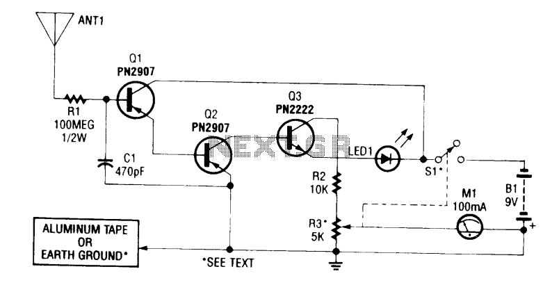
The detector is designed to sense static charges and free ions present in the air. It can indicate the presence of ion emissions, high voltage, static electricity, and electrostatic fields. The grounding can be achieved through an earth ground...
Most homes today have at least a few infrared remote controls, whether for the television, video recorder, stereo, or other devices. Despite this, many individuals have experienced frustration when a light remains on after settling into a comfortable chair...