
Infrared Proximity Detector Alarm
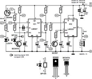
This circuit is designed to detect the presence of nearby objects using infrared light and sound an alert via an acoustic actuator. The operation begins with the infrared emitter D1, which emits a pulsed beam at a frequency of 20 kHz. The average current flowing through D1 is controlled by R1, ensuring efficient operation and preventing overheating. The pulsed nature of the current is managed by T1 and IC1, which work together to maintain the specified duty cycle.
When an object reflects the infrared beam back towards the receiver diode D2, the reflected signal is captured and processed by IC1. The LM567 PLL is adept at locking onto the 20 kHz frequency, allowing for reliable detection of the reflected signal. The output from IC1, upon detecting the signal, triggers the 555 timer (IC2) to activate the acoustic actuator Bz1, producing an audible alert.
In addition to the primary detection and alerting functions, the circuit incorporates a timing mechanism. The 555 timer remains active as long as the reflected infrared signal is present. In the absence of a signal, capacitor C5 charges through R9, and the 555 timer will deactivate after approximately 5 seconds, providing a clear indication of the end of the detection period.
Careful consideration is given to the placement of D1 and D2 to ensure that D2 is only responsive to the reflected infrared light and not to ambient light sources. The circuit's performance may require minor adjustments to R4 to optimize the receiver's sensitivity based on environmental conditions.
Overall, this circuit represents a practical application of infrared technology combined with sound signaling, suitable for various applications such as object detection and proximity sensing. The use of low-cost components enhances its accessibility for hobbyists and engineers alike.This circuit can be built from readily available low-cost components, some of which may even be hiding in your junkbox! The indicated value of 22 for resistor R1 causes an average current of about 65 mA through infrared emitter D1.
Because the IRED is pulsed at a duty factor of about 50% through the action of T1 and IC1, a peak current of 128 mA flows during every half cycle. This may seem a lot but in fact is well within the safe specication of the LD274. The LM567 PLL IC is configured to supply a switching frequency of about 20 kHz. When the infrared beam emitted by D1 is reflected by a nearby object, IC1, through receiver diode D2 and transistor T2, receives the recovered 20 kHz signal at its input, pin 3. Because the 567 PLL is then locked, the IC output (pin 8), drops low, triggering the 555 chip in monostable mode (IC2) and so causing acoustic actuator Bz1 to sound.
The monostable remains on as long as the re‚ected signal is being received. Because of the presence of T3, capacitor C5 is allowed to charge only when no signal is being received. In that condition, the 555 is turned off automatically after a time determined by R9-C5. Using the component values shown, this will be about 5 seconds. Obviously D1 and D2 should be mounted such that the latter can only pick up re‚ected infrared light. The choice of the two infrared components used in this circuit will be uncritical but they must be band` compatible, i.
e. , generate (D1) and respond to (D2) the same wavelength. The operating point of the receiver input circuit is rather dependent on ambient day-light levels and the value of R4 may need to be adjusted a little to ensure a voltage of between 1. 5 V and 4 V on the collector of T1 when no signal is being received. Some dc buzzers cause a lot of back-emf so it may be necessary to insert a diode in series with the output of IC1.
If necessary, this diode should preferably be a Schottky type because of the inherent low voltage drop of about 0. 4 V as opposed to 0. 65 V for a typical small-signal silicon diode. 🔗 External reference
Related Circuits
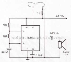
The circuit of a burglar alarm utilizing IC timer 555/556 functions as a security measure to prevent unauthorized entry into a premises. The alarm generates a loud sound when a thin wire connecting resistor R1 with pin 4 of...
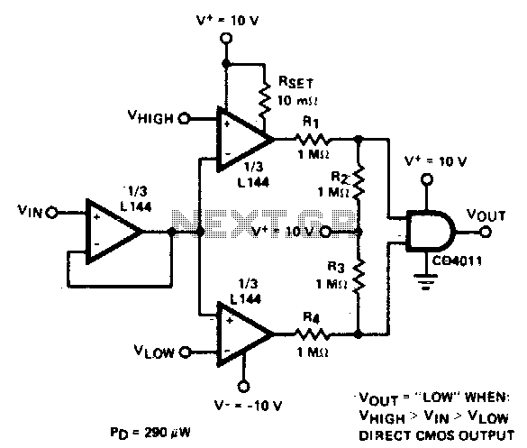
The detector employs three sections of an L144 and a CMOS NAND gate to create a low-power voltage monitor. The 1 MΩ resistors R1, R2, R3, and R4 convert the bipolar ±10 V swing of the operational amplifiers to...
The operation of this receiver is analogous to human perception. Humans perceive colors and respond based on what they observe. Similarly, phototransistors react to the intensity of infrared light directed at them. The key distinction is that humans possess...
Most homes today have at least a few infrared remote controls, whether they are for the television, video recorder, stereo, etc. Despite this fact, Infrared (IR) remote controls are ubiquitous in modern households, serving as convenient devices for operating...

This compact water sensor alarm circuit emits a loud warning sound when a humidity sensor detects the presence of water. The circuit utilizes the low-power comparator LM1801 from National Semiconductor. A fixed reference voltage for the integrated circuit is...
Infrared interruption counter is a reliable circuit that takes over the task of counting number of interruptions very accurately. When somebody enters into the room, then the Counter is Incremented by one. The total number of Persons inside the...