
Infrared Remote Controls
The circuit operates by first receiving an infrared signal through the MOD, which is sensitive to specific modulation frequencies. The 40 kHz signal is crucial for the MOD to recognize valid commands, while the 4 kHz modulation ensures that the circuit can differentiate between noise and actual signals. The resistor R1 and capacitor C1 form a low-pass filter that determines the sensitivity of the MOD. By increasing the resistance or capacitance, the circuit can become less responsive to ambient light, thereby reducing false triggers.
Once the MOD detects a valid infrared signal, it outputs a low signal to the 4013 flip-flop, which is configured in a toggle mode. The 4013 IC is a dual D-type flip-flop that can store binary states. Each time it receives a low signal from the MOD, it toggles its output state. This toggling action serves as a control mechanism for the MOC optical coupler, which is designed to isolate the low-voltage side of the circuit from the high-voltage AC load.
The MOC optical coupler plays a critical role by providing electrical isolation between the control circuit and the AC load. When the output from the 4013 goes high, the MOC activates, allowing current to flow through its output side. This current triggers the triac, which is a semiconductor device capable of controlling AC power. The triac remains on until the current flowing through it drops below a certain threshold, effectively allowing the circuit to control the power to the connected AC device.
In summary, this circuit represents an effective solution for wirelessly controlling AC-powered devices using infrared signals. By adjusting the components to suit specific environmental conditions, users can achieve reliable operation while maintaining safety through electrical isolation.This circuit will allow you to turn on any piece of equipment that operates on 115 volts ac. The reciever circuit is based on the Radio Shack infrared receiver module(MOD), part number 276-137. It is also available from some of the other sources listed on my Links page. The MOD accepts a 40khz IR signal that is modulated at 4 khz. When a signal is recieved the MOD will go low. The sensitivity of the MOD is set by different values for R1 and C1. The values for R1 may need to be as high as 10, 000 ohms and for C1 40uf. This will prevent the unit from turning on under normal lighting conditions. You will need to experiment with the vaules that work best for you. The output of the 4013 chip a flip flop toggles on and off with the reception of a IR pulse. The output of the 4013 turns on the MOC optical coupler which in turn switches on the triac and supplies power to the AC load. 🔗 External reference
Related Circuits

In August 2007, an individual with a passion for photography acquired a Panasonic FZ30 digital camera and joined a forum on dpreview dedicated to Panasonic products. A fellow forum member, who was a programmer and electronics enthusiast, created a...

This device functions as a convenient tool for testing infrared (IR) remote control transmitters used with televisions, VCRs, and similar devices. The IR signals emitted from a remote control are detected by the IR sensor module within the tester,...
The latest addition to the collection of Infrared (IR) Repeater circuits, the Mark 5, is a significantly enhanced version of the Mark 1 circuit, featuring improved range and sensitivity. It is designed to be immune to the effects of...
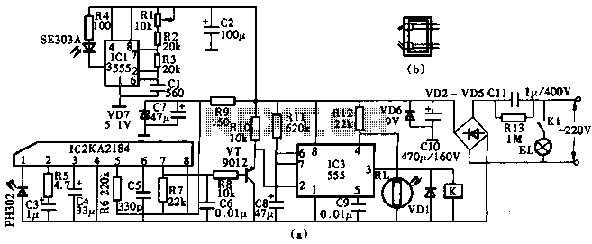
This circuit utilizes the KA2184 infrared receiver ASIC for an infrared remote control dimmer light application, as depicted in the schematic. The infrared signal is generated by a pulse generator using an NE555 timer integrated circuit. The NE555 produces...
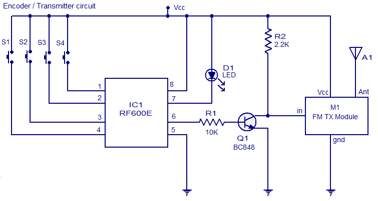
The circuit diagram illustrates an FM remote encoder/decoder utilizing the RF600E and RF600D integrated circuits (ICs). These components are engineered to deliver a high level of security and operate within a voltage range of 2 to 6.6V DC. Applications...

A high-quality preamplifier with tone controls consisting of three circuits. The NE5532 is chosen as the main integrated circuit due to its ultra-low noise properties, making it a popular choice in fine audio applications. Although these circuits are older...