
Infrared Remote Tester
The infrared remote control tester circuit is designed to provide a straightforward method for verifying the functionality of remote controls. The core components include a photo transistor, an LED, and a few passive components such as resistors. When a button on the remote control is pressed, infrared light is emitted from the remote's IR LED. This emitted light is detected by the photo transistor (Q1), which is sensitive to infrared wavelengths.
The circuit operates by converting the infrared light signal into an electrical signal that activates the LED indicator. When the photo transistor receives sufficient infrared light, it allows current to flow, turning on the LED. The flashing of the LED serves as a visual indication that the remote control is functioning properly.
The design emphasizes simplicity and low power consumption, making it ideal for quick checks without the need for complex equipment. With a current draw of less than 1 mA during operation, the circuit is efficient and can be powered by a small battery. The omission of the switch (SW1) is justified by the low power requirements, allowing for a continuous readiness to detect signals without unnecessary components.
To ensure optimal performance, the user should maintain a distance of 20 to 25 cm between the remote control and the tester. This range allows for effective detection while minimizing the effects of ambient light interference. The straightforward nature of this circuit makes it an excellent tool for electronics amateurs and professionals alike, providing a reliable means of troubleshooting and testing infrared remote controls efficiently.A very simple device allowing a quick check of common Infra-red Remote-Controls can be useful to the electronics amateur, frequently asked to repair or test these ubiquitous devices. A reliable circuit was designed with a handful of components: the LED will flash when any of the Remote-Control push buttons will be pressed.
The side of the Remote-C ontrol bearing the IR emitting diode(s) must be directed towards the Photo Transistor (Q1) of the checker circuit: maximum distance should not exceed about 20 - 25cm. Current drawing of the circuit is less than 1mA when the LED illuminates and 0mA when no signal is picked-up by the Photo Transistor: therefore, SW1 can be omitted.
🔗 External reference
Related Circuits
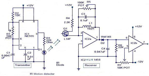
The following circuit illustrates an Infrared Motion Sensor circuit diagram. Features include the use of the NE555 integrated circuit, with a detection zone coverage of 80 degrees. The Infrared Motion Sensor circuit utilizes the NE555 timer IC configured in a...
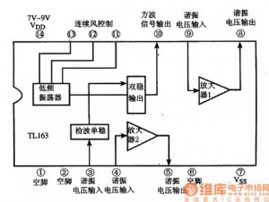
The following circuit illustrates the TL163 integrated circuit (IC) used in an ultrasonic remote control circuit diagram. Features include a detector, high-gain amplifier, and low-frequency response. The TL163 IC is designed to facilitate ultrasonic signal processing, making it suitable for...
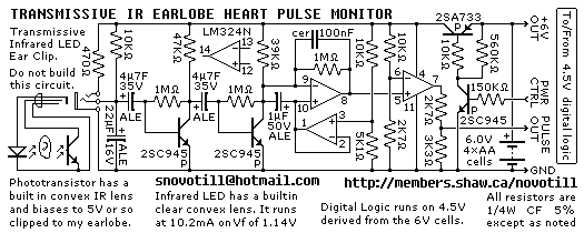
Senses heart pulse by means of an infrared earlobe clip. Reverse engineered circuit diagram of heart pulse sensor circuit board out of a treadmill. Notice that the output is level shifted for use by CMOS logic running on 4.5V...
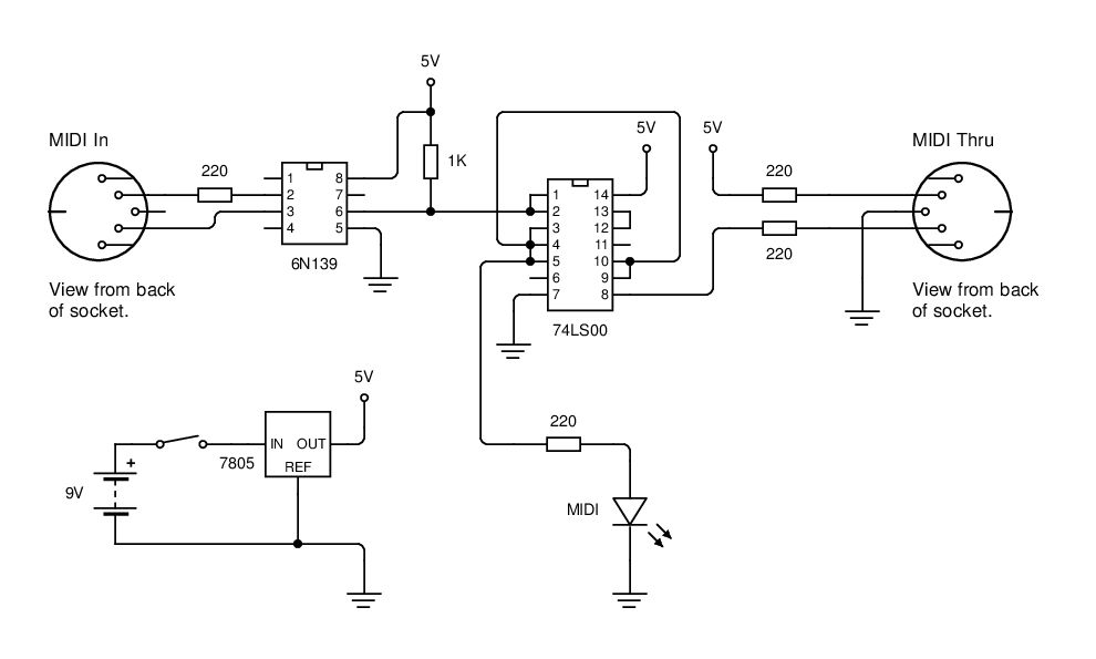
MIDI data is transmitted between instruments using a current loop, and an opto-isolator (6N139) is employed to convert this current loop into TTL pulses. The circuit utilizes the 6N139 opto-isolator to separate the MIDI signal from the receiving device, ensuring...
This circuit is intended for precision centigrade temperature measurement, with a transmitter section converting to frequency the sensor's output voltage, which is proportional to the measured temperature. The output frequency bursts are conveyed into the mains supply cables. The...
A continuity tester is useful for verifying that there is a conductive path between two points. This circuit offers the advantage of being highly sensitive, providing both visual and audible indications of continuity. An audible tester is particularly beneficial...