
Instrument Cluster 1987-1993 Ford Mustang Wiring Diagram
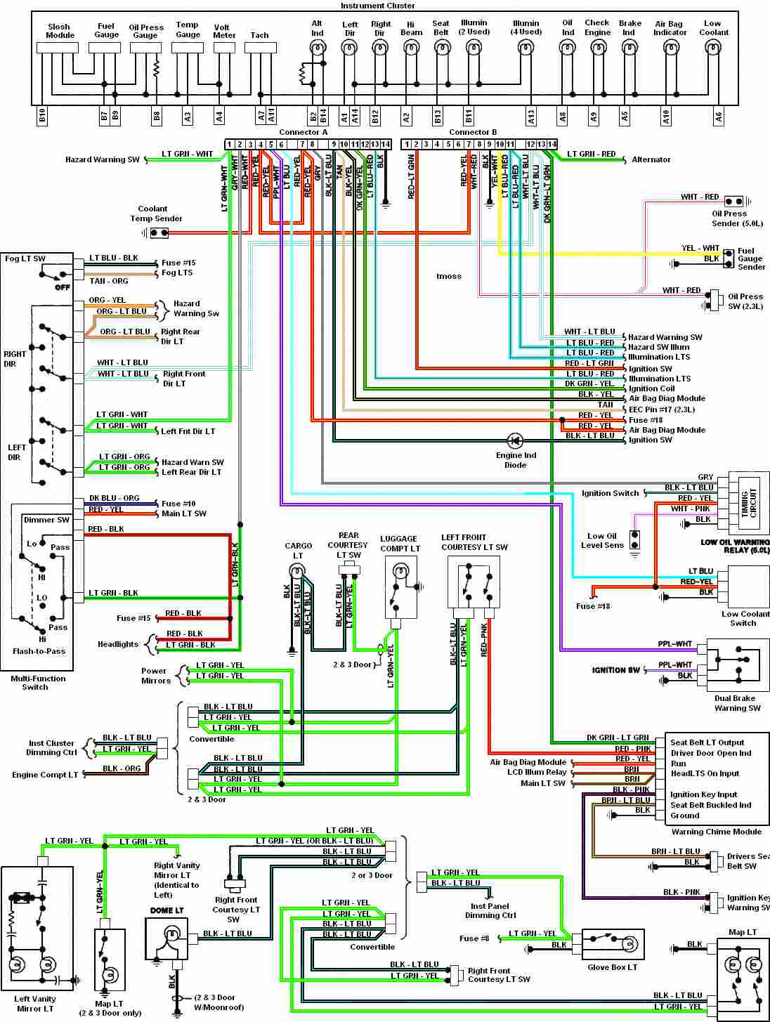
The instrument cluster for the 1987-1993 Ford Mustang serves as a critical interface for the driver, providing essential information about the vehicle's operational status. This cluster typically includes various gauges and indicators that display information such as speed, fuel level, engine temperature, and warning lights for various systems within the vehicle.
The schematic of the instrument cluster consists of several key components. The speedometer is driven by a cable connected to the transmission, which translates the rotational speed of the vehicle into a readable speed format. The fuel gauge operates by measuring the resistance of a float mechanism within the fuel tank, allowing for an accurate display of fuel levels. The engine temperature gauge utilizes a thermistor that changes resistance with temperature variations, providing real-time feedback on engine heat.
In addition to these gauges, the cluster contains warning lights for critical systems such as oil pressure, battery voltage, and check engine, ensuring that the driver is promptly alerted to any issues that may arise. The cluster is powered by the vehicle's electrical system, typically receiving power through a dedicated fuse.
The layout of the instrument cluster is designed for optimal visibility and accessibility, with gauges positioned for easy reading while driving. The use of backlighting enhances visibility in low-light conditions. The integration of a printed circuit board (PCB) within the cluster facilitates connections between the various components, allowing for efficient signal transmission.
Overall, the instrument cluster of the 1987-1993 Ford Mustang is a vital component that enhances driver awareness and vehicle safety, encapsulating a blend of mechanical and electronic functionalities to deliver critical vehicle data.Automotive diagram for Instrument Cluster of 1987-1993 Ford Mustang (Third Generation). 🔗 External reference
Related Circuits
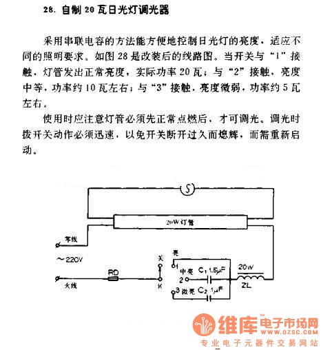
A homemade 20W fluorescent lamp dimmer utilizes a series capacitor connection to effectively control the brightness of fluorescent lamps, allowing for adaptability to various lighting requirements. In the modified circuit diagram (Figure 28), when the switch is set to...
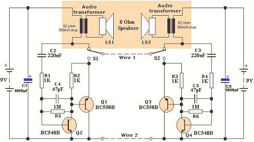
Wiring 2-Wire Intercom. According to Wikipedia, an intercom is a stand-alone electronic communications system intended for limited or private dialogue. A 2-wire intercom system is designed to facilitate communication over a limited distance, typically within buildings or residential areas. The...
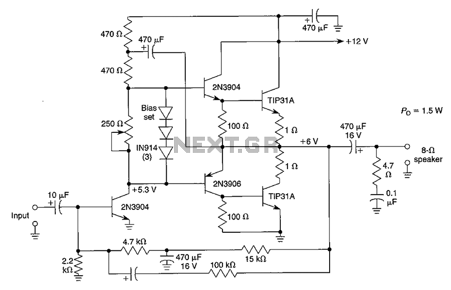
Although the integrated circuit (IC) has largely replaced this circuit, the flexibility of the discrete device design still makes it practical. The components are readily available and cannot easily be eliminated. If desired, a small piece of metal can...
1995 Nissan Altima Brake and Tail Light Wiring Diagram. The wiring diagram for the brake and tail lights of the 1995 Nissan Altima provides a visual representation of the electrical connections and components involved in the lighting system. This diagram...
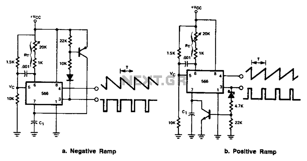
The 566 can be connected to either a positive or negative ramp generator. For a positive ramp generator, an external transistor is driven by the output pin 3. At the end of charging, C1 discharges quickly, allowing for immediate...
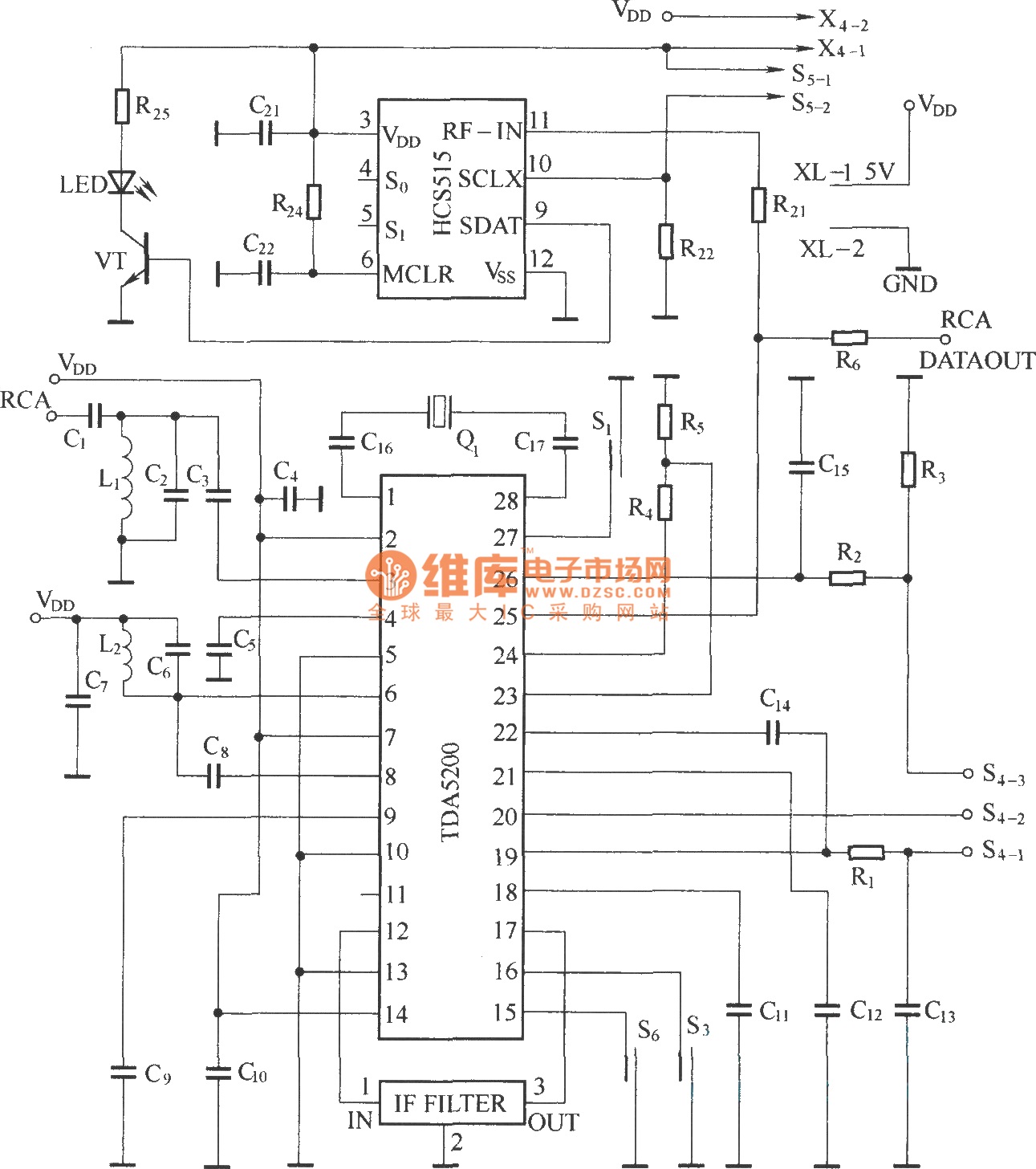
The TDA5200 is a low-power, single-chip ASK superheterodyne receiver circuit. It operates within two frequency blocks: 868 to 870 MHz and 433 to 435 MHz. This circuit is highly integrated, requiring minimal external components while offering excellent functionality. It...
Warning: include(partials/cookie-banner.php): Failed to open stream: Permission denied in /var/www/html/nextgr/view-circuit.php on line 713
Warning: include(): Failed opening 'partials/cookie-banner.php' for inclusion (include_path='.:/usr/share/php') in /var/www/html/nextgr/view-circuit.php on line 713