
Instrumenting an Earth Satellite
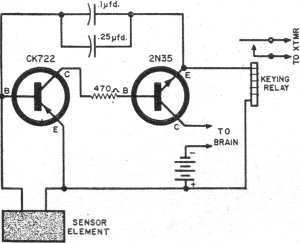
Ground Control: The ground control setup includes a modified radio control transmitter operating at 27.255 MHz and three receivers; one tuned to the satellite's transmitter frequency of 820 kHz, while the other two are tuned to 1220 kHz and 1300 kHz. To conserve battery power, one of the satellite's transmitters remains silent until activated by the ground transmitter. The satellite is equipped with a two-transistor receiver to detect the R/C ground interrogation signal, which automatically activates the "Brain" and its instrumentation cycle. The basic circuit of the telemetering system is depicted in a schematic. The pulse rate of the unit, functioning like a metronome, is adjusted using a resistance-changing sensor instead of a variable resistor. These sensors include a thermistor for temperature measurement, a photocell for ultraviolet light detection, and an erosion gauge for micrometeorite monitoring. The erosion gauge can be a mirror with its paint backing carefully removed or a photocell with an opaque coating. In the case of the former, the "sandblasting effect" from micrometeorites erodes some of the silver from the back of the mirror, altering the resistance, while in the latter, the erosion allows more light to reach the cell. Consequently, the pulse rate of the sensor-pulser unit corresponds to the measured phenomenon.
Instrumentation Cycle: The output from these units is amplified, and each pulse activates the transmitter through a keying relay. Each pulser is switched on, connected to the appropriate sensors, and linked to the transmitter via the "Brain." This component consists of a timed 22-position five-deck stepping relay that advances one position every five seconds, enabling Argus I to execute a programmed instrumentation cycle.In October of 1958 when this article was written, a mere year had passed since the successful launch of Sputnik and a few months later the launch of Echo satellites - the first ever for Russia and the USA, respectively. Prior to that time all satellites were conglomerations of rock, metal, and/or gas. There were no manmade satellites except for a couple remnants of test rockets that happened to reach orbital heights.
That Ronald Michael Benrey, a highschooler of the day, would design and enter an "Earth Satellite" to demonstrate some of the technology needed to an actual orbiting satellite was a phenom. Most people hadn`t even learned to spell "satellite" yet. His creation took second place in the National Science Fair and first prize in the USAF`s Awards Program.
Webster`s definition of Argus is incomplete. In Greek mythology, Argus has another connotation - it denotes the starry heavens. In all respects, it is a fitting name for a model satellite - "Argus I" - built by Ronald Michael Benrey and entered in the National Science Fair. The satellite took second prize at the Fair and took first prize in the Air Force`s Awards Program, as well as receiving other citations.
While it doesn`t have the 100 eyes of the mythological Argus, it does have seven "eyes" - sensors designed to "see" such things as temperature, ultraviolet light, and micrometeorites-as well as two "voices" - transmitters to relay the information to receivers. A view of the "works" in Argus I. Note that almost all components are cased in plastic to allow full visibility - the metal box at bottom houses the "Brain".
With the antennas in place, "Argus I" measures 54" in diameter and weighs 20 pounds. With batteries, it weighs 30 pounds. It is completely transistorized, using 15 transistors in all. Total cost of the project was about $200. Ground Control. When set up, the ground control equipment consists of a modified radio control transmitter operating on 27. 255 mc. and three receivers, one tuned to the constant frequency of satellite transmitter Number I (820 kc. , ) and the other two to the frequencies of transmitter Number II (1220 and 1300 kc. ). To conserve battery power, one of the satellite`s transmitters is silent until keyed by the ground transmitter.
The satellite carries a two-transistor receiver to pick up the R/C ground interrogation signal, automatically keying the "Brain" into its instrumentation cycle. The basic circuit in the telemetering system is shown in the schematic. The pulse rate of the unit (a metronome, in effect) is varied by using a resistance changing sensor in place of a variable resistor.
Such sensors include a thermistor for temperature, photocell for ultraviolet rays, and erosion gauge for micrometeorites. The erosion gauge is a mirror with the paint backing carefully removed with a cotton pad dipped in nail polish remover, or it can be a photocell with an opaque coating.
In the case of the former, the "sandblasting effect" of micrometeorites erodes some of the silver from the back of the mirror, changing the resistance; in the case of the latter, the erosion allows more light to get through to the cell. In this way the sensor-pulser unit`s pulse rate is a function of the phenomenon measured. Instrumentation Cycle. The output of these units is amplified and each pulse keys the transmitter via a keying relay. Each pulser is turned on, hooked to the proper sensors and connected to the transmitter by the "Brain.
" This consists of a "timed" 22-position five-deck stepping relay which advances one position every five seconds, giving "Argus I" a programmed instrumentation c 🔗 External reference
Related Circuits
A circuit has been identified that integrates a voltage regulator and filter to isolate the voltage supplied by the receiver for powering an operational amplifier (op-amp) that drives a meter. Additionally, the circuit isolates the carrier frequency from the...
The intentions for night air charging have been deemed possible but unnecessary. During late March and early April, the heating system operated effectively at night due to favorable air temperatures compared to glycol temperatures, which proved beneficial. With the...
The purpose of the Kapagen is to suck the free electrons from the Earth. The Earth is a big capacitor which contains free electric charges. If it is possible to create or to find a potential imbalance between two...
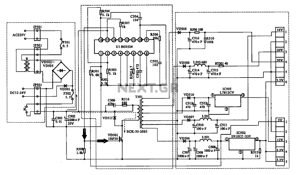
The Changhong DVB-2000 digital satellite receiver features a switching power supply circuit. This circuit primarily comprises a power input section, an oscillation switching circuit, and a DC output section. The power input circuit receives 22V AC from a step-down...
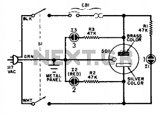
The circuit is straightforward and reliable when connected properly. Under standard operating conditions, only lamps 1 and 3 should illuminate. If lamp 2 activates, it indicates that the cold lead is at 117 volts above ground. The described circuit operates...
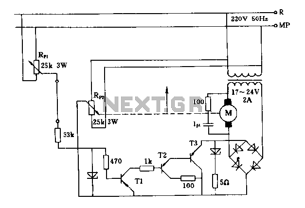
The FIG potentiometer RP2 has a sliding contact that is directly connected to the antenna. The system operates such that only when potentiometers RP1 and RP2 are positioned identically, do the non-conductive transistors and rectifier bridge remain off, resulting...
Warning: include(partials/cookie-banner.php): Failed to open stream: Permission denied in /var/www/html/nextgr/view-circuit.php on line 713
Warning: include(): Failed opening 'partials/cookie-banner.php' for inclusion (include_path='.:/usr/share/php') in /var/www/html/nextgr/view-circuit.php on line 713