
Interactive Toy Traffic Lights
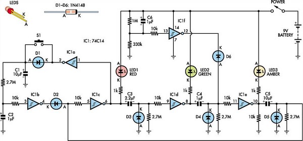
The circuit design employs a hex Schmitt-trigger inverter IC, which is advantageous for its ability to provide clean switching and noise immunity. The use of colored LEDs allows for clear visual indication of the traffic signal states, enhancing user interaction and comprehension. The timing sequence is meticulously defined by the RC time constants set by the capacitors and resistors, ensuring that each LED is illuminated for the specified duration. The inclusion of diodes for discharging timing capacitors is a critical design feature, preventing unintended illumination of subsequent LEDs while the current LED is still active. The pushbutton functionality is integrated into the circuit in a manner that allows for immediate response, enhancing the user experience by providing a quick way to alter the red light duration. Overall, the circuit is a straightforward yet effective implementation of a traffic signal using basic electronic components, showcasing the principles of timing, sequencing, and user interaction in electronic design.This toy traffic signal uses a single low-cost hex Schmitt-trigger inverter IC (IC1a-IC1f) to directly drive three coloured LEDs (red, green and amber). At switch-on, the circuit lights the red signal for 30s, then shows green for 6s, then amber for 3s. It then repeats the sequence. Interaction is provided by pushbutton S1 which abbreviates the re d period to a further 3s only, if it is pressed while the red signal is showing. Sequencing of the three LEDs is controlled by inverters IC1c, IC1d & IC1e, while the electrolytic capacitors at the inverter outputs and their associated 2. 7MO resistors determine how long each LED stays on. Diodes D3, D4 & D5 discharge the timing capacitors for the next two LEDs in the sequence while the current LED is on.
Note also the 10kO resistor at the input of each inverter. These protect the inverter inputs from being damaged by the negative voltage produced when the previous output goes low while its timing capacitor is fully charged. The circuit is forced into the red state at switch-on by IC1f and its associated circuitry. What happens is that IC1f briefly pulls the negative end of the amber timing capacitor (C4) low via D6 at switch-on.
As a result, IC1e`s output goes high and turns the amber LED (LED3) off. The red timing capacitor (C5) is in a discharged state at power-up because D5 and the 10kO resistor at the output of IC1e discharge it when the power is off. As a result, when IC1e`s output goes high, IC1c`s output goes low and turns LED1 (red) on. This also pulls the input of IC1d low, so IC1d`s output goes high, turning the green LED off. The amber timing capacitor (C4) at the output of IC1d charges rapidly when it receives the negative pulse from IC1f.
That`s because its positive end is high when the green LED is off and the pulse takes its negative end low. When pin 12 of IC1f subsequently goes high at the end of the switch-on pulse, this remains charged and holds the input of IC1e low, so the amber LED (LED3) remains off.
Pushbutton operation is controlled by IC1a and IC1b, which rapidly charge the red timing capacitor (C5) 3s after switch S1 is pressed. This works as follows: pin 2 of IC1a is high when the red LED is on, so pressing S1 during the red period rapidly charges C1.
C2 then charges slowly from C1 via a 2. 7MO resistor. After about 3s, C2 reaches IC1b`s trigger threshold and so pin 4 of IC1b switches low. Because the red LED is on, the amber LED is off. This means that pin 10 of IC1e is high and so the positive end of C5 is also high. When IC1b`s output goes low, it pulls the negative end of C5 low via D2, thereby rapidly charging this timing capacitor. This ends the red period and so the red LED (LED1) turns off. As a result, IC1a`s output goes low and C1 and C2 discharge via D1, ready for the next time switch S1 is pressed.
🔗 External reference
Related Circuits
The terminal of R7, indicated by an arrow, must be connected to the desired output pin of IC2 or IC3 to select the number of LEDs or clusters that will form the bar. For instance, to drive seven LEDs...
This circuit enables the brake light to flash. The default behavior occurs when power is supplied to the circuit or when the brake is engaged. The timer IC (IC2) drives current to the transistor (Q2), producing an oscillating output...
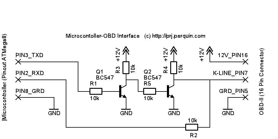
The interface illustrated below can be utilized to construct a serial cable that connects the serial port of a computer to the 16-pin OBD-II connector found in many vehicles manufactured from 1996 onwards. This interface exclusively supports the ISO...
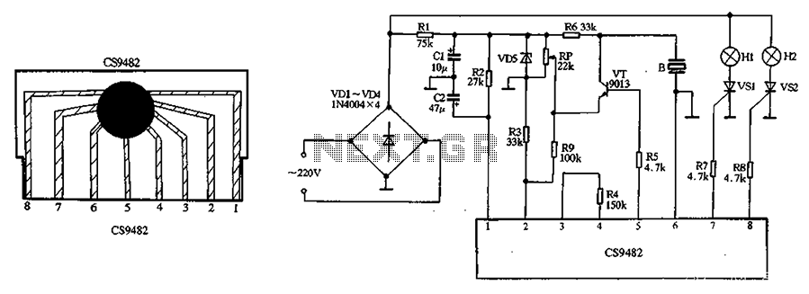
The CS9482 integrated circuit fabrication is demonstrated with a holiday lights circuit. The CS9482 chip includes a 4.1V voltage regulator circuit; therefore, while the external circuit does not need to be regulated, if the voltage exceeds 4V, a current-limiting...
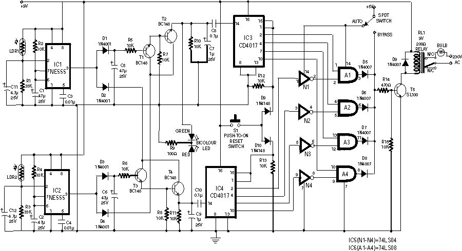
The circuit employs two Light Dependent Resistors (LDRs) arranged in series with a separation of approximately half a meter. This configuration allows each LDR to detect the presence of a person entering or exiting the room. The processed outputs...
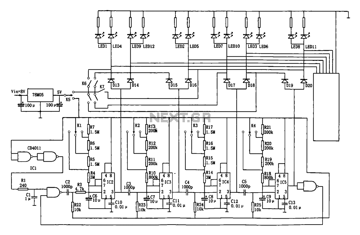
This document describes an automatic traffic intersection light control circuit. It features four monostable delay circuits, which consist of four 555 timer integrated circuits (IC2 to IC5) and several RC components interconnected. An 8V input voltage is regulated through...
Warning: include(partials/cookie-banner.php): Failed to open stream: Permission denied in /var/www/html/nextgr/view-circuit.php on line 713
Warning: include(): Failed opening 'partials/cookie-banner.php' for inclusion (include_path='.:/usr/share/php') in /var/www/html/nextgr/view-circuit.php on line 713