
Intercom Circuit
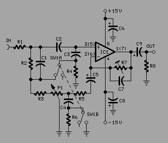
This intercom circuit utilizes an 8-ohm speaker in a dual role, functioning as both the input (microphone) and output (listening speaker) device. The design leverages the inherent properties of the speaker to convert sound waves into electrical signals and vice versa. The 10K potentiometer serves as a variable resistor, allowing the user to adjust the volume level of the audio output.
In the schematic, the speaker is connected in parallel with a preamplifier stage, which is essential for boosting the weak audio signals captured by the speaker when used as a microphone. The output of this preamplifier is then fed into an operational amplifier (op-amp) circuit, which further enhances the signal strength. The gain of the op-amp can be adjusted using feedback resistors, allowing for fine-tuning of the audio levels.
The 10K potentiometer is strategically placed in the circuit to provide a user-friendly interface for volume control. By varying the resistance of the potentiometer, the signal level sent to the output stage can be increased or decreased, enabling the user to achieve the desired listening volume without introducing significant distortion.
Power supply considerations are also crucial in this design. The circuit typically requires a DC power source, which can be derived from batteries or a wall adapter. Proper decoupling capacitors should be included to filter out any noise from the power supply, ensuring clean audio performance.
Overall, this intercom schematic presents a simple yet effective design for audio communication, utilizing common components to achieve functionality and ease of use. The dual-purpose speaker and adjustable gain through the potentiometer make it an efficient solution for basic intercom applications.In this intercom schematic, the 8 ohm speakers is used as microphone and listening speaker. The 10K potentiometer controls volume and the total gain can be.. 🔗 External reference
Related Circuits
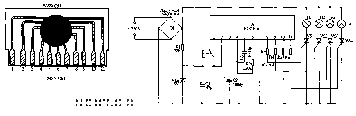
The circuit utilizes a 220V AC input, which is converted to DC using a VD1-VD4 bridge rectifier. This rectified voltage is used to power four lights (H1 to H4). The circuit also includes a resistor (R1) for voltage limiting...
The receiver circuit and display module will receive the high-frequency AC power cord and decode it to provide actual temperature readings using digital IC No. CD4553 (Three-digit BCD Counter IC) and IC CD4511 (BCD-to-7-Segment Latch/Decoder/Driver IC). The frequency pulses...
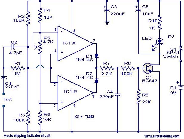
This circuit is designed to detect clipping in a specific waveform. Clipping occurs when the amplitude of a waveform decreases before reaching its expected limit. The circuit activates an LED as an indication that the tested signal is experiencing...
The circuit indicates two different water temperature trip points by activating LEDs when the specified temperatures are reached. It is built around the LM2904 dual operational amplifier, which is powered by a 12 V automotive system. A thermistor is...
ETl3X220 is a cost-effective single-chip transmitter that operates via RF communication. It supports up to 10 channels and is ideal for applications such as wireless mice, keyboards, and other communication devices. The main technical features include: - Analog FM...
To achieve optimal audio reproduction at various listening levels, it is essential to incorporate tone-setting controls that align with the well-documented characteristics of human auditory perception. Specifically, human ear sensitivity exhibits a non-linear response across the audible frequency spectrum,...
Warning: include(partials/cookie-banner.php): Failed to open stream: Permission denied in /var/www/html/nextgr/view-circuit.php on line 713
Warning: include(): Failed opening 'partials/cookie-banner.php' for inclusion (include_path='.:/usr/share/php') in /var/www/html/nextgr/view-circuit.php on line 713