
Interface between Ericsson 6xx/7xx phones and a PC

The described interface serves as a crucial bridge between devices operating on different voltage levels and communication protocols. The MAX232 integrated circuit is specifically designed to convert signals from TTL (Transistor-Transistor Logic) levels, which range from 0 to 5 volts, to RS232 levels, which can vary from -12 to +12 volts. This conversion is essential for ensuring compatibility between the phone and the PC's serial port, preventing potential damage that could arise from direct connection.
The circuit typically includes the MAX232 IC, which requires a few external components for proper operation, including capacitors that help in voltage conversion and regulation. The MAX232 uses a charge pump to generate the necessary negative voltage for RS232 communication. Commonly, this involves four external capacitors (usually 1µF) connected to specific pins of the IC to facilitate the charge pumping process.
The S1 switch serves a dual purpose in this interface. It can be used to toggle between different operational modes or to enable/disable the connection to the phone, providing flexibility in usage. The phone System Connector is specifically designed to interface with the phone's communication port, and its pin configuration must be adhered to for proper connectivity and functionality. For detailed pin-out information, consulting the pin-out page is essential to ensure correct wiring and avoid misconnection.
Overall, this interface is a practical solution for connecting a phone to a PC while ensuring that both devices operate within their respective voltage and signal requirements, thus maintaining the integrity and functionality of both devices.This interface is needed to connect the phone to a PC, because the PC`s serial port works with voltage levels between -12 and 12V (RS232 protocol) and the phone operates between 0 and 5V (TTL protocol). Don`t even think in conecting your phone directly to the serial port, this would certainly damage your phone and/or the PC serial port!!!
The interface main component is IC1 - MAX232, a common IC in RS232 - TTL interfaces, with some external components wich are needed for the IC to work correctly. The main difference between this and other interfaces is the S1 switch and the phone System Connector.
To get more info about the System connector, like pin.out, go to the pin-out page. 🔗 External reference
Related Circuits
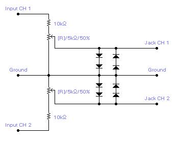
For simple electronic circuits, it may be sufficient to gain qualitative insights on dedicated electrical signals. This interface circuitry allows the line-in input of a standard PC sound card to be utilized as a 2-channel oscilloscope. Although this setup...
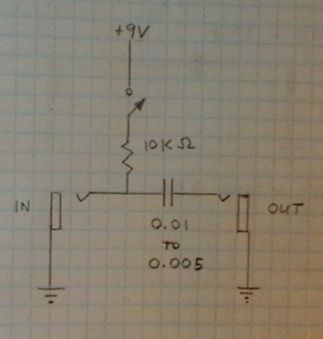
Condenser microphones generally provide superior sound quality compared to dynamic microphones. For those unfamiliar with these two microphone types, a Wikipedia article can offer useful insights. Electret condenser microphones consist of two plates (capacitors), one of which vibrates in...
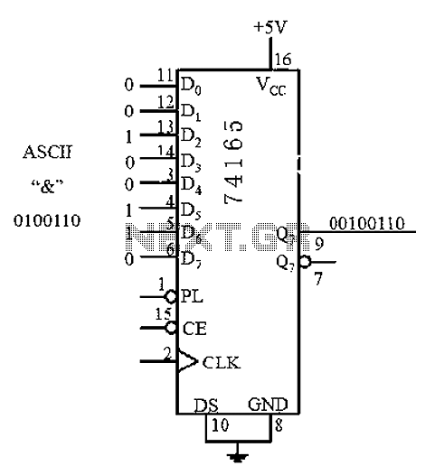
An 8 parallel input/serial output interface circuit. An 8 parallel input/serial output interface circuit is designed to convert multiple parallel data inputs into a single serial output stream. This type of circuit is commonly used in digital systems where data...
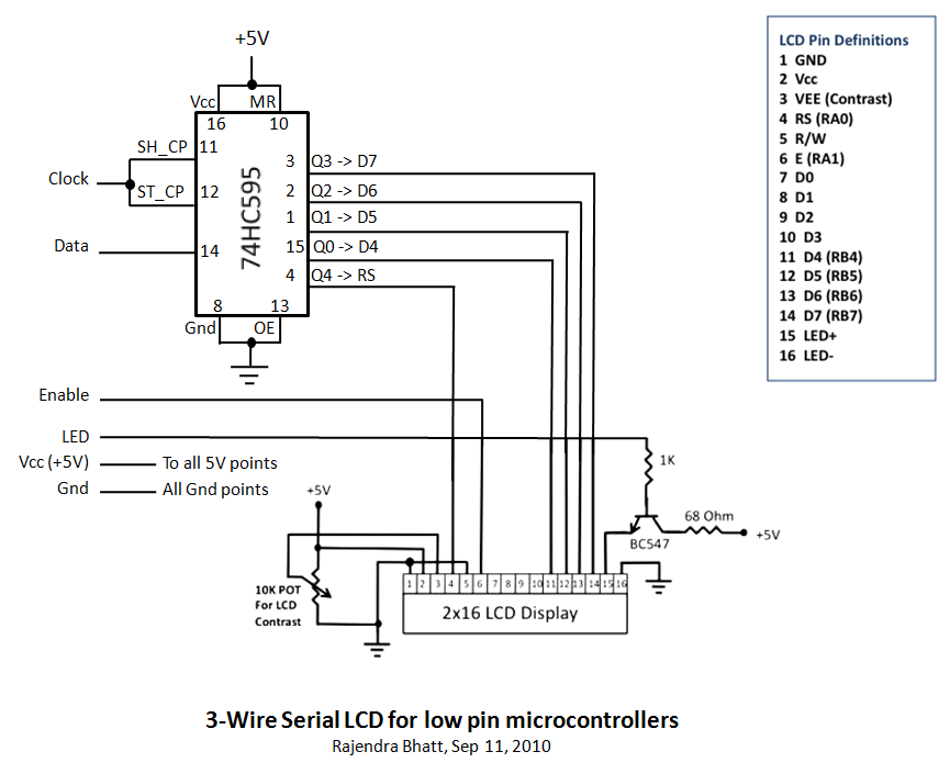
Library routines for a 3-wire LCD interface utilizing the 74HC595 shift register. Additional details can be found in the attached ReadMe document or on the associated webpage. The library routines for the 3-wire LCD interface are designed to facilitate communication...

This circuit is designed for general-purpose use with a large LED display utilizing SPI serial interfacing. It employs a serial-in-parallel-out shift register, specifically the 74HC595, to receive serial data from a microcontroller board. The schematic wiring indicates that SER...
This circuitry facilitates the connection between the computer's Z RS-23 serial interface and the current ring circuitry. It converts the voltage signal of the transmission into a current signal of 20 mA, achieving a maximum speed of 1200 bits....