
Interfacing LCD to Atmega using two wires
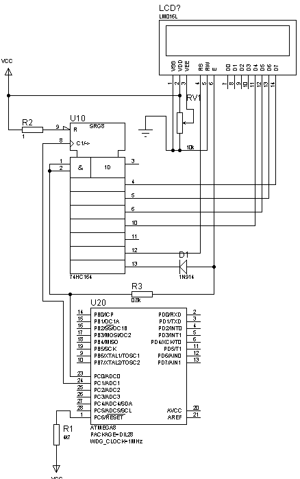
The circuit utilizes a shift register, specifically the 74HC164, to enable communication with the LCD while minimizing the number of required microcontroller pins. The shift register operates by receiving serial data, which is clocked in through the PC1 pin of the Atmega microcontroller. The PC0 pin serves as the data input line for the shift register. This configuration allows for efficient data transmission to the LCD.
To initialize the shift register, it is essential to clear it before any data is written. This is accomplished by sending eight clock cycles of zeros, ensuring that the register is in a known state. After initialization, the data is sent in a specific format: the first bit is always a high signal to trigger the LCD strobe, followed by a Register Select signal that indicates whether the following data is a command or display data. The subsequent bits include the actual data to be displayed, with the last bit set low to maintain proper timing for the strobe signal.
The use of a resistor and diode in conjunction with the shift register creates a logical AND gate. This ensures that the LCD E pin is only activated when both the data line is high and the Q7 output of the shift register is also high. This design effectively prevents erroneous signals from being sent to the LCD, thereby enhancing the reliability of the display.
In summary, this circuit allows for the effective interfacing of an LCD with minimal pin usage by employing a shift register to convert serial data into the parallel format required by the LCD. This approach is particularly useful in applications where microcontroller resources are limited, enabling the display of information without sacrificing pin availability.This is not new Idea of interfacing LCD using two wires, but it can help in many situations when there is not enough of microcontroller pins. This example is based onHitachi 44780 Alphanumerical LCD. This circuit I provide is only to represent an idea but I think it should work also if soldered. We know, that to make LCD working you need at least 6 (in 4 bit mode) wires to control. But what if you need as many pins as possible from your avr and still want to see results on LCD. Then you need to use serial LCD or make one. In this example you just need to convert serial data coming to LCD using shift register. I suggest using 74HC164. You need only two wires to push data to shift register and then give them to LCD using a‚ Ea‚ strobe signal. Atmegaa‚ s PC1 pin clocks shift register and PC0 is data line. Before you write to shift register clean it by sending a‚ 0a‚ in eight clock cycles. You can erase register with additional wire controlling register reset, but there would be 3 lines used.
After register is cleared, send eight bits to register. First bit sent is always 1, as it is used to strobe LCD, second bit is Register Select, and then one bit is not used and then follows 4 bits as data and las bit is always 0 in order to make strobe E work correctly. You should see that in eight clock cycle last bit in shift register enables LCD with a‚ 1a‚ value in last bit.
Then by sending 1 ³ to data line you enable LCD E pin. Resistor and Diode acts there as AND element. If only register Q7 signal is active, but data low, then LCD E pin is low. If data line is high but 74HC164 register Q7 pin is low, then diode pulls low this signal and LCD pin will be low. Only when both PC0 and shift register Q7 are high, ten LCD pin E is strobed. We aim to transmit more information by carrying articles. Please send us an E-mail to wanghuali@hqew. net within 15 days if we are involved in the problems of article content, copyright or other problems.
We will delete it soon. 🔗 External reference
Related Circuits
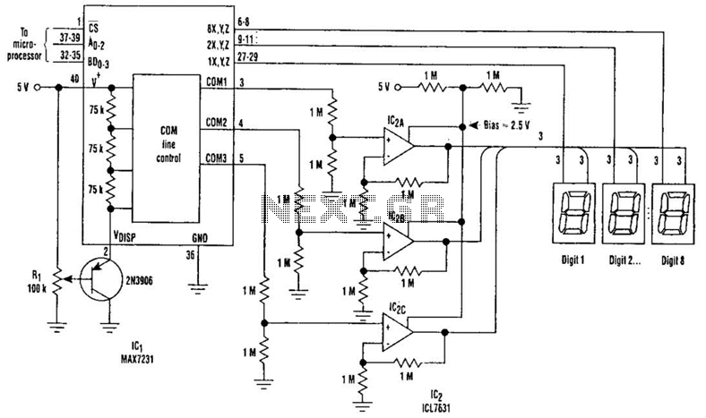
Large LCD devices with one or more displays exhibit significant driving capacitance to the driver circuits. To address this issue, the drive circuit incorporates a buffer amplifier for each of the three common lines. Each amplifier can be programmed...
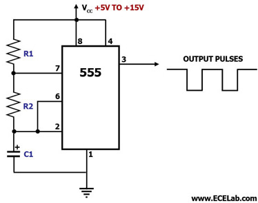
This circuit diagram illustrates the configuration of a 555 timer integrated circuit (IC) as an astable multivibrator. An astable multivibrator is a timing circuit characterized by unstable 'low' and 'high' states. Consequently, the output of an astable multivibrator continuously...
An individual is attempting to design an alarm using an LM555 timer but is unsure of where to begin. Friends who have experience in designing alarms are providing support. The LM555 timer is a versatile integrated circuit widely used in...
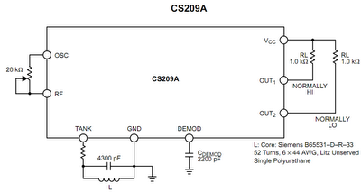
The operation principle of the proposed metal detector circuit is straightforward yet intriguing. The detection function is activated by sensing a decrease in the quality factor (Q) of the LC network associated with the circuit when a metal object...
Using a switch to power up your microcontroller projects may not be a good idea if you need to "wake" the PIC during some events. For example: A metal detector sends a pulse indicating a car is ready to...
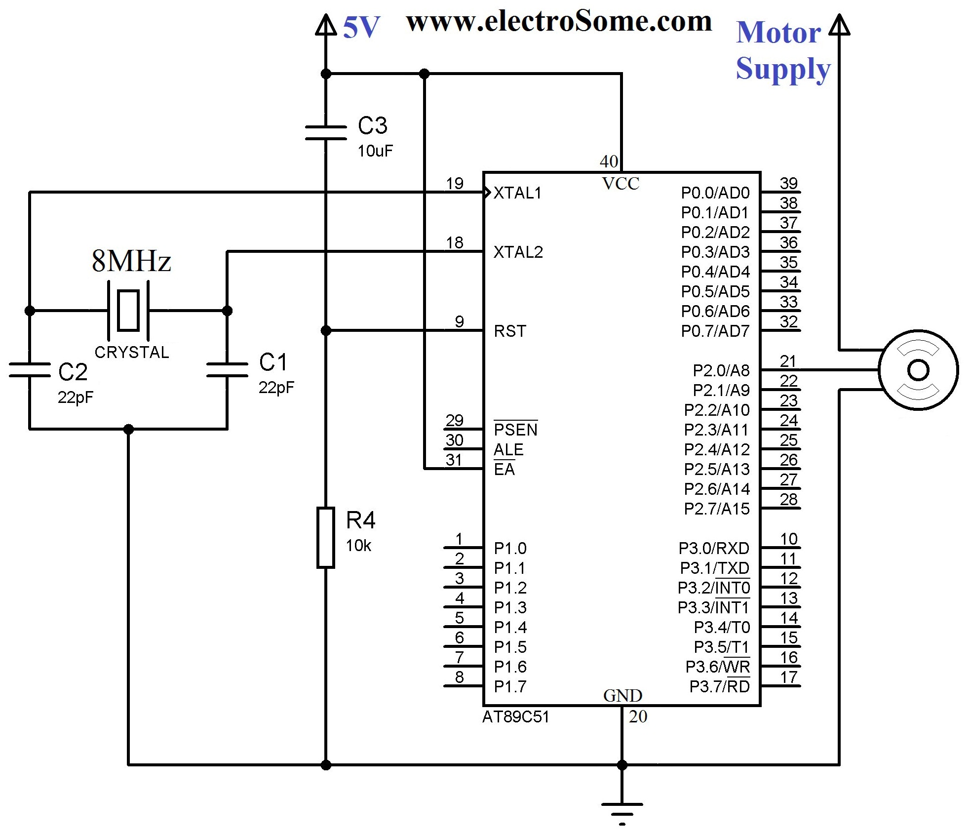
A servo motor employs a servo mechanism, which is a closed-loop system that utilizes position feedback to accurately control the angular position of its shaft. Stepper motors, which operate as an open-loop system, can also achieve precise angular control,...
Warning: include(partials/cookie-banner.php): Failed to open stream: Permission denied in /var/www/html/nextgr/view-circuit.php on line 713
Warning: include(): Failed opening 'partials/cookie-banner.php' for inclusion (include_path='.:/usr/share/php') in /var/www/html/nextgr/view-circuit.php on line 713