
interfacing servo motor with 8051 using keil c
The provided code snippet includes the necessary instructions for controlling the servo motor through the 8051 microcontroller. The servo motor control is initiated by setting the motor_pin to low, followed by a loop that sequentially rotates the motor to 0 degrees, 90 degrees, and 180 degrees. Each position is achieved by sending a high signal to the motor_pin for a specific duration, determined by the Delay_servo function, which introduces a delay in microseconds. The main function executes this loop indefinitely, allowing continuous operation of the servo motor. The Delay function introduces a longer delay in milliseconds, while the Delay_servo function is designed for finer control of the servo's movement timing. This setup is essential for applications requiring precise angular positioning, ensuring that the servo motor operates smoothly and accurately within its defined range.A servo motor uses servoG‚ mechanism, which is a closed loop mechanism that uses position feedback to control the precise angular position of the shaft. Stepper Motors, which is an open loop system can also be used for precise angular control. But Servo Motors are preferred in angular motion applications such as robotic arm. G‚Moreover controlling of servo motors are very simple, easy and needs no extra hardware like stepper motor. Usually hobby circuit servo motors have three wires. Two of them are red and black which is used to give power to the motor and the third wire is used to provide control signal for angular position. It uses Pulse Width Modulated ( PWM ) waves as control signals. The angle of rotation is determined by the width of the pulse at the control pin. The servo motor used here is having angle of rotation from 0 to 180 degrees. We can control the exact angular position by varying the pulse betweenG‚1msG‚to 2ms. Before using this in your application, please refer the datasheet of your servo for angle and pulse width informations.
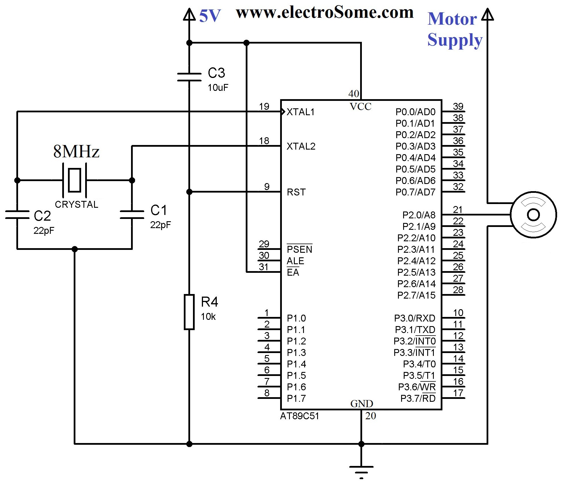
8MHz crystal is used to provide the required clock for 8051 microcontroller and 22pF capacitors are used to stabilize the operation of crystal. 10KG © resistor and 10G F capacitor is used to provide the required Power On Reset (POR) to the microcontroller.
Control of Servo Motor is connected to first pin of Port 2. #include
Related Circuits
The large servos shown alongside a Nokia 3310 mobile phone provide a reference for scale. The servo arms measure 12 cm in length, making them suitable for lifting a bank of solar panels. The local Model Aerodrome in Seaside...
Ralph Stirling, KC3F, and another engineer developed the first generation of a digital signal processing (DSP) system using the Texas Instruments C5X DSK starter kit. The second generation represents a significant advancement, utilizing the more appropriate Motorola DSP56002EVM evaluation...
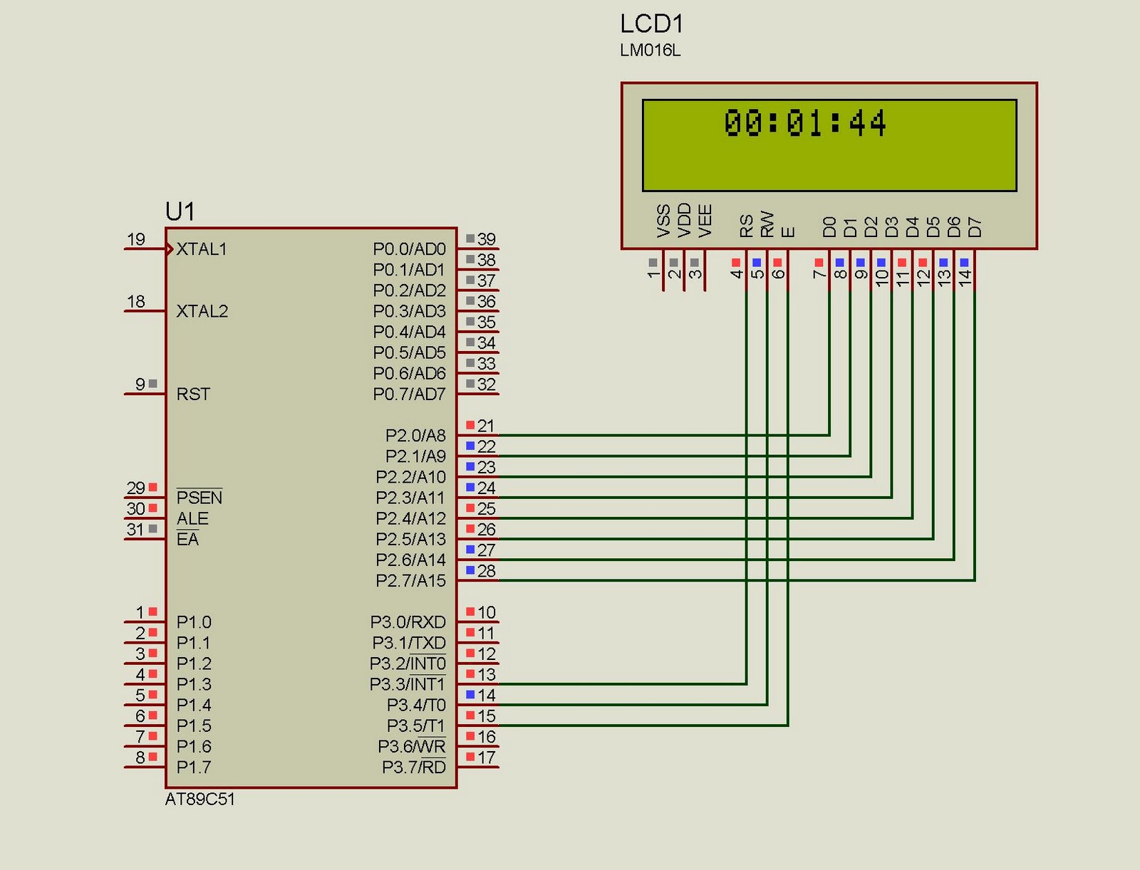
This project implements a real-time clock using the 89C51 microcontroller. The clock's data format is hours:minutes:seconds, which is displayed on a 16x2 LCD. The code has been tested and compiled using the Keil uVision compiler. The circuit diagram for...
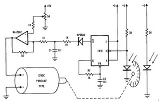
A simple encoder circuit for a DC motor can be constructed using the provided circuit diagram. The system includes the HA-2542 operational amplifier, a small 12 V DC motor, and a position encoder. During operation, the encoder generates a...
This is a simple servo tester which will comprehensively test the capabilities of almost any modern servo. It has two pushbuttons, CENTRE and SWEEP and a potentiometer which works as follows: CENTRE Does exactly that, centers the servo, afterwards...
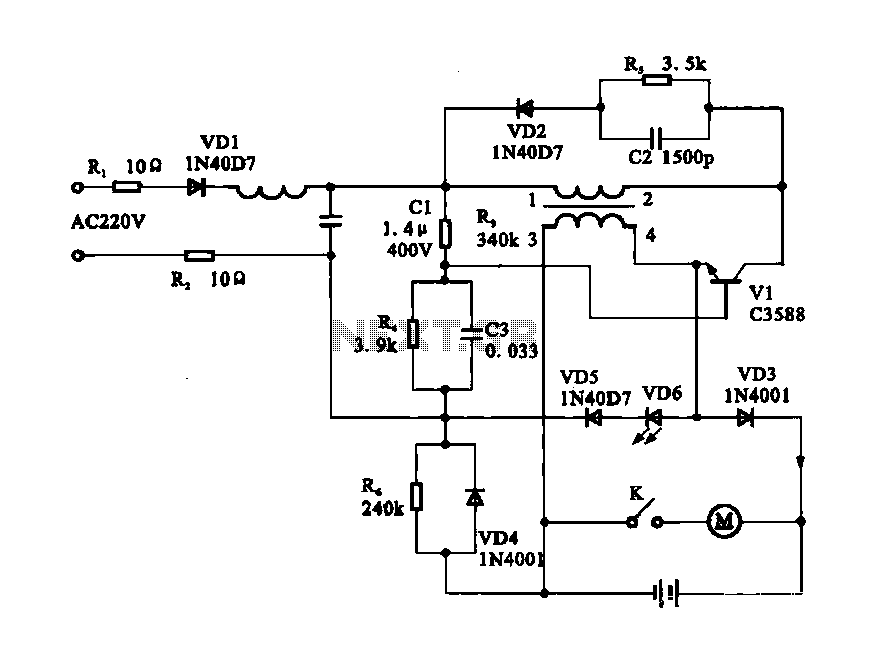
Electric shaver motor drive circuit. It illustrates a typical motor drive circuit for an electric shaver. AC 220V is used to charge the battery through the charging circuit, which also provides power to the motor. After activating the charge-on...
Warning: include(partials/cookie-banner.php): Failed to open stream: Permission denied in /var/www/html/nextgr/view-circuit.php on line 713
Warning: include(): Failed opening 'partials/cookie-banner.php' for inclusion (include_path='.:/usr/share/php') in /var/www/html/nextgr/view-circuit.php on line 713