
Interfacing to External EEPROM
The provided code demonstrates how to interface with an external Microchip EEPROM using I2C for random read and write operations. The code is structured to initialize the I2C communication, write data to a specified address, and read data back from that address.
The I2C protocol is employed in this project, with specific configurations for the hardware I2C controller. The EEPROM write command is represented by the address 0xA0, where the last bit indicates a write operation (0). Conversely, the read command is represented by the address 0xA1, with the last bit set to 1 for read operations.
The code includes functions for writing and reading from the EEPROM. The `rand_write` function initiates the I2C bus, sends the write command along with the target address (split into high and low bytes), and then sends the data to be written. A delay of 5 milliseconds is implemented to allow the EEPROM to complete the write operation, as specified in the datasheet.
The `rand_read` function similarly starts the I2C bus and sends the write command to set the address. It then restarts the I2C bus to switch to read mode, retrieves the data from the specified address, and concludes the operation by releasing the bus.
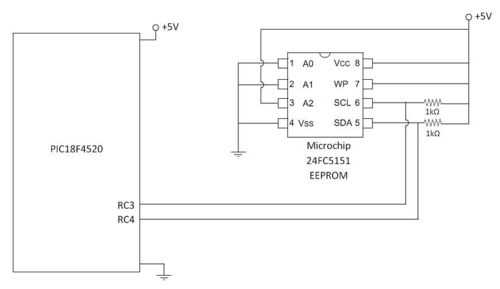
The main function initializes a reference output, performs a random write operation, and subsequently reads the data back, outputting it for verification. The design emphasizes the capability of random access within the EEPROM, showcasing its utility in applications requiring flexible data storage solutions.An external EEPROM can be useful for several different reasons. External EEPROMs allow much more data to be stored than is available on the 18F4520. In addition, EEPROM memory saves state when power is removed. In this project, we interfaced to a Microchip EEPROM in random read/write mode. "Random" write mode specifies that the memory locations ac cessed do not come in any sequential form. Although one can use this mode to access data sequentially in the EEPROM, there is a different protocol structure for sequential reads that increases throughput. In this project, we only developed the random write protocol. PIN1 and PIN2, A0 and A1 are hardware addressing bits, they correspond to 0xA0 (writing data) and 0xA1 (reading data).
The first 4 bits are internally set to 1010 (A) and the second four correspond to the block of memory (0 or 1), A0 and A1 (hardware addressing we set to low in this circuit diagram) and read/(NOT write). PIN7, WP is the write protect line which has two states. When connected to logic high, normal read/write operation can be performed. When this pin is set low, only read operations are permitted. /* eeprom_rand_access. c Scott McLeod 03-05-2008 This program shows how to interface to an I2C extrenal Microchip EEPROM. This code is written for random reads and writes to the EEPROM */ #include <18f4520. h> #fuses HS, NOLVP, NOWDT, NOPROTECT #use delay(clock=20000000) #use i2c(MASTER, FAST, SCL=PIN_C3, SDA=PIN_C4, FORCE_HW) // use hardware i2c controller int8 EEPROM_WR = 0xA0; // I2C Address.
1010 0000. last bit = 0 => write command // First Nibble is fixed as 1010 (internal address); // Second Nibble is ABCD, // A = Block Set // B, C = Hardware Addresses (Configured when you Wire the CHIP) // D = (0 = write, 1 = read) int8 EEPROM_RD = 0xA1; // Same as EEPROM_WR except last bit = 1 for READ command int read = 0; int data = 128; int16 loc; int temp = 0; void rand_write(int16 address, int data) { i2c_start(); // Claim I2C BUS i2c_write(EEPROM_WR); // Tell all I2C devices you are talking to EEPROM in WRITE MODE i2c_write(address>>8); // Address High Byte (0x00 - 0x) i2c_write(address); // Address Low Byte (0x00 - 0xAA) i2c_write(data); // Data to write i2c_stop(); // Release BUS delay_ms(5); // Let EEPROM Write Data (5ms from data sheet) } int rand_read(int16 address) { i2c_start(); // Claim I2C BUS i2c_write(EEPROM_WR); // Tell all I2C devices you are talking to EEPROM in WRITE MODE // (you are first writing to the EEPROM to set the address. Later you will read) i2c_write(address>>8); // Address High Byte (0x00 - 0x i2c_write(address); // Address Low Byte (0x00 - 0xAA) i2c_start(); // RESTART I2C BUS (necissary for microchip protocol) i2c_write(EEPROM_RD); // Tell all I2C you are talking to EEPROM in READ MODE.
read = i2c_read(); // Read in the data i2c_read(0); // Read last byte with no ACK i2c_stop(); // release the bus return(read); } void main() { output_d(1); // Output a 1 for reference to start delay_ms(1000); // *Not necissary pause, just for debugging loc = 0x00; // Random Location in memory temp = 15; // Byte to write rand_write(loc, temp); // Random Write: rand_write(address, data) output_d(255); delay_ms(1000); // *Not necissary pause, just for visual purposes temp = 0; // Reset temp temp = rand_read(loc); // Random Read: rand_read(address); output_d(temp); // Output temp while(true) { } } 🔗 External reference
Related Circuits
This EEPROM programmer is designed to read, write, and erase 24C EEPROM devices. It features a PC serial port interface and requires a 5V DC power supply. The programmer can read or write one page (16 bytes) at a...
A servo motor employs a servo mechanism, which is a closed-loop system that utilizes position feedback to accurately control the angular position of its shaft. Stepper motors, which operate as an open-loop system, can also achieve precise angular control,...
A clock oscillator is commonly utilized in digital signal processing circuits and microprocessor circuits. Digital signal transmission and signal processors necessitate a clock, which serves as the system's timing signal, while the data signal functions as a synchronization signal....
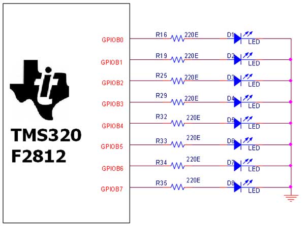
The TMS320F2812 Evaluation Board is specifically designed for developers in the digital signal processing (DSP) field, as well as for beginners. The F2812 kit is structured to allow easy access to all the features of the DSP. The TMS320F2812...

An 8051 program must interact with external devices that facilitate communication with users. One of the most prevalent devices connected to an 8051 microcontroller is an LCD display. Common types of LCDs used with the 8051 include 16x2 and...
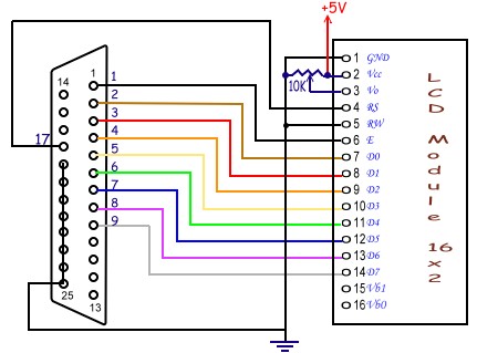
Tutorial on interfacing the 20x4 LCD module to the PC parallel port. The interfacing of a 20x4 LCD module with a PC parallel port involves several steps, which include hardware connections, software setup, and programming. The 20x4 LCD module is...