
Internal modem schematics
The internal SoftV92 Data Fax Modem operates by converting digital signals from a computer into analog signals suitable for transmission over a telephone line and vice versa. The modem connects to the phone line through a standard RJ-11 connector. It typically includes various components such as a digital signal processor (DSP), a microcontroller, and several capacitors and resistors that facilitate signal processing and modulation.
In the schematic, the phone line interface is depicted, showing the connection points for the telephone line and the modem circuitry. The line interface circuitry often includes protection elements to prevent damage from voltage spikes, which can occur during lightning strikes or power surges. The modem's internal components work together to handle data transmission rates up to 56 Kbps, adhering to the V.92 standard.
The schematic may also highlight the power supply connections, which are essential for the operation of the modem. It is common for these modems to derive power from the host computer's power supply through the PCI or PCIe interface. Additionally, the diagram may include the arrangement of various integrated circuits (ICs), such as the modem controller, which manages the data flow and communication protocols.
Understanding this schematic can assist technicians and engineers in diagnosing issues related to connectivity, signal quality, or hardware malfunctions in similar modems. By following the layout and connections indicated in the diagram, users can perform repairs or modifications to restore functionality to malfunctioning units.This diagram shows how an internal SoftV92 Data Fax Modem interacts with phone line. The modem is from Zoltrix but a Conexant utility says it is a "Churchill Data Modem". This schematic may be useful to fix a similar modem. 🔗 External reference
Related Circuits
A Nidec TA450DC B35502-35 fan has been installed in a large wooden cabinet housing a computer and other electronics, which generates significant heat. The fan is designed to draw air from the room and exhaust it through openings at...
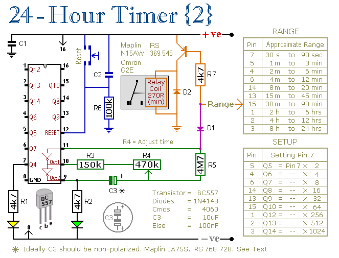
These two circuits are multi-range timers that offer periods of up to 24 hours and beyond. They can function as repeating timers or single-shot timers. Both circuits are fundamentally the same, with the primary distinction being their behavior in...
Using a magnetic compass, ensure that both pickups have a South polarity on the top of each pickup. Verify this by checking for a North polarity on the bottom of the pickups. It is uncommon to find both pickups...
This document was created to address the numerous inquiries received about how to read a schematic. Learning to interpret a schematic diagram is akin to map reading; it requires understanding which wires connect to which components and identifying the...
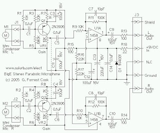
The mini condenser microphone converts sounds into an electrical signal. Resistor R1 provides bias for the condenser microphone's internal amplifier transistor. The 2N3906 PNP transistor acts as a low-noise microphone input amplifier. The 10K gain potentiometer is used for...

The clock circuit is constructed using a stable oscillator that consists of two inverters integrated into IC1 and a watch crystal that oscillates at 32.768 kHz. This frequency is divided by 16384 through the internal flip-flop chain of IC1,...