
Inverting amplifier using opamp. Practical opamp amplifier circuit and waveforms
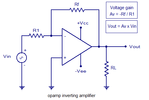
An inverting amplifier is a fundamental configuration of operational amplifiers that provides a phase-inverted output signal relative to the input signal. The circuit typically consists of a single op-amp, two resistors, and a power supply. The basic principle of operation relies on the virtual ground concept, where the inverting input of the op-amp is held at a constant voltage (typically 0V) due to negative feedback.
The voltage gain (Av) of the inverting amplifier can be expressed with the equation:
\[ Av = -\frac{R_f}{R_{in}} \]
where \( R_f \) is the feedback resistor connected between the output and the inverting input, and \( R_{in} \) is the resistor connected from the input signal to the inverting input. The negative sign indicates that the output is inverted.
The output voltage (\( V_{out} \)) can be calculated using the formula:
\[ V_{out} = Av \cdot V_{in} = -\frac{R_f}{R_{in}} \cdot V_{in} \]
In practical applications, the 741 operational amplifier is commonly used due to its availability and reliability. The circuit configuration involves connecting the non-inverting input to ground, while the input signal is applied to the inverting input through \( R_{in} \). The feedback loop is completed by connecting \( R_f \) from the output back to the inverting input.
Input and output waveforms can be analyzed to demonstrate the inverting nature of the amplifier. When a sinusoidal input signal is applied, the output will be an inverted sinusoidal waveform, maintaining the same amplitude but 180 degrees out of phase. This characteristic makes the inverting amplifier suitable for various applications, including signal processing, audio amplification, and analog computing.
It is essential to consider the bandwidth and slew rate of the op-amp, as these factors can influence the performance of the inverting amplifier in high-frequency applications. Additionally, the choice of resistor values can affect the noise performance and stability of the circuit.Inverting amplifier using opamp. Equations for voltage gain and output voltage, input and output waveforms, practical inverting amplifier circuit using 741 IC etc.. 🔗 External reference
Related Circuits
This week involved the completion of several objectives. Initially, software was downloaded to design the schematic for a circuit intended for translation onto a PCB. A significant portion of the week was dedicated to tutorials and familiarization with the...
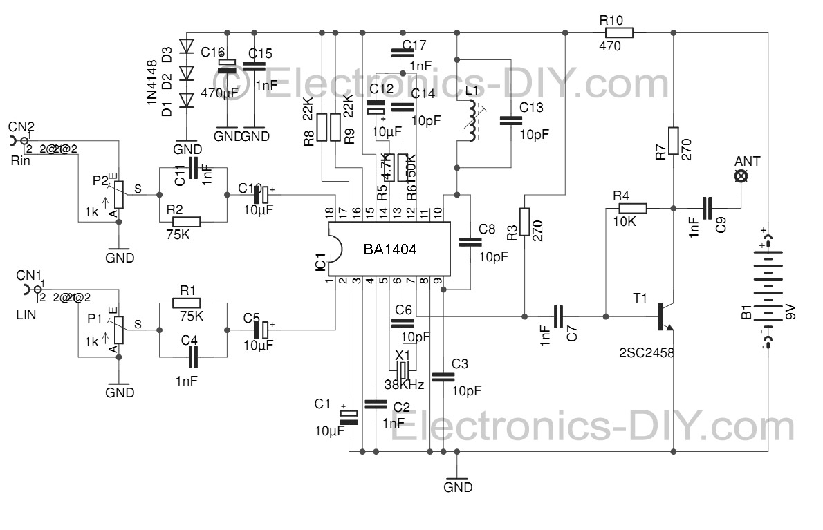
This Stereo FM Transmitter with BA1404 enables the creation of a mini stereo FM station, allowing for wireless audio broadcasting throughout a home. It provides a straightforward method for establishing an audio link without the need for complex wiring....
This is a circuit diagram of an audio amplifier circuit featuring a 10W power amplifier using the TDA2003 integrated circuit from SGS Thomson. The IC is capable of delivering 10W into a 4-ohm load at a supply voltage of...

The schematic for the board is illustrated below. The three primary components of the board include (1) the power input and voltage regulation, (2) the L297 input and outputs, and (3) the L298 stepper motor control circuit. The motor...
The 7208 seven-stage decimal counter can be utilized as a frequency counter. It features latch and multiplexing functions, along with direct digital driving circuitry and display driving circuitry. The output frequency of the 7207 IC 6.5536 MHz crystal oscillator...
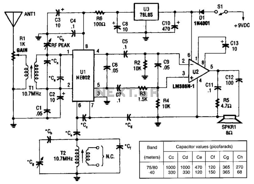
An NEC602 is utilized as a mixer with a zero intermediate frequency (IF) output, while U2 functions as an audio amplifier. This receiver is mainly designed for single sideband (SSB) and continuous wave (CW) signals. T1 and T2 are...