
IP phone to analog phone or modem audio interface circuit
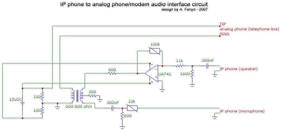
The circuit utilizes a 600:600 ohm transformer, which serves as an impedance-matching device between the IP phone and the associated audio components. The transformer’s design, with equal turns on both coils, ensures minimal signal loss and optimal performance at the specified load impedance. The inductance of 75 mH suggests that the transformer can handle a range of audio frequencies effectively, making it suitable for voice transmission.
Variable resistors are employed to fine-tune the impedance match. The resistor near the speaker is critical for adjusting the amplification of the audio output, which is essential for achieving clear sound quality. The high-value resistor, set at approximately 10K ohms, allows for greater control over the signal amplification. The second variable resistor, designed to operate at a lower value, is crucial for managing the input signal from the microphone, ensuring that the output level is appropriate for the IP phone's input specifications.
The inclusion of two 100 ohm resistors, each dissipating around 600 mW, necessitates careful selection to prevent overheating. Using resistors rated for higher power dissipation, such as 150 ohms, can enhance reliability and performance.
The circuit also incorporates two 300 nF capacitors in conjunction with their associated resistors, forming high-pass filters that effectively mitigate low-frequency noise and assist in echo cancellation. The cutoff frequency of approximately 300 Hz is strategically chosen to filter out unwanted low-frequency signals, thereby enhancing the clarity of voice transmission.
The observations made during the testing phase, particularly regarding the headphone output and its transfer function, highlight the importance of understanding the acoustic characteristics of audio devices. The identification of the Head Relative Transfer Function (HRTF) emphasizes the need for precise calibration in audio applications, particularly in environments where spatial audio perception is critical.
Overall, this circuit design provides a robust solution for interfacing an IP phone with audio components, ensuring optimal performance through careful impedance matching, filtering, and signal amplification techniques.The transformer is a 600:600 ohms transformer (also named 1:1 ratio 600 ohm transformer) : more or less the same number of turns on both primary and secondary coils, and optimized to work at 600 ohms load. Selectronic sells one here. I measured the primary and secondary coils on the one from Selectronic: about 75 mH inductance and 50 ohms
resistance. - the variable resistors need to be fine tuned for operating at best impedance match with the IP phone. The one near the IP phone speaker will probably need to be tuned at a high value (about 10K ohms); it directly controls the amplification of the signal you ear.
The other needs to be very low since it is only here to attenuate the level at which your voice is sent to the IP phone, since the microphone you replaced with this module probably sends a lower signal than this module. - the two 100 ohms resistors will dissipate about 600 mW each : avoid using those standard low-cost half watt resistors (or use 150 ohms standard ones instead.
). - the two 300 nF capacitors (and their associated resistors) act as high-pass first order filters (Fc is about 300 Hz) to eliminate noise and perform echo cancellation. While I was conceiving this telephone interface circuit, I used my Sound Blaster Extigy sound card from Creative Labs as a function generator.
I encountered weird effects and I realized the headphones output had a not so good transfer function. I plotted the voltage transfer function with my APPA 106 multimeter. Here it is: After weeks having bad dreams about this weird transfer function, I suddenly realized, one night, that it was obviously a Head Relative Transfer Function (HRTF) !
Here is a plot of a standard HRTF (extracted from this web site ): 🔗 External reference
Related Circuits
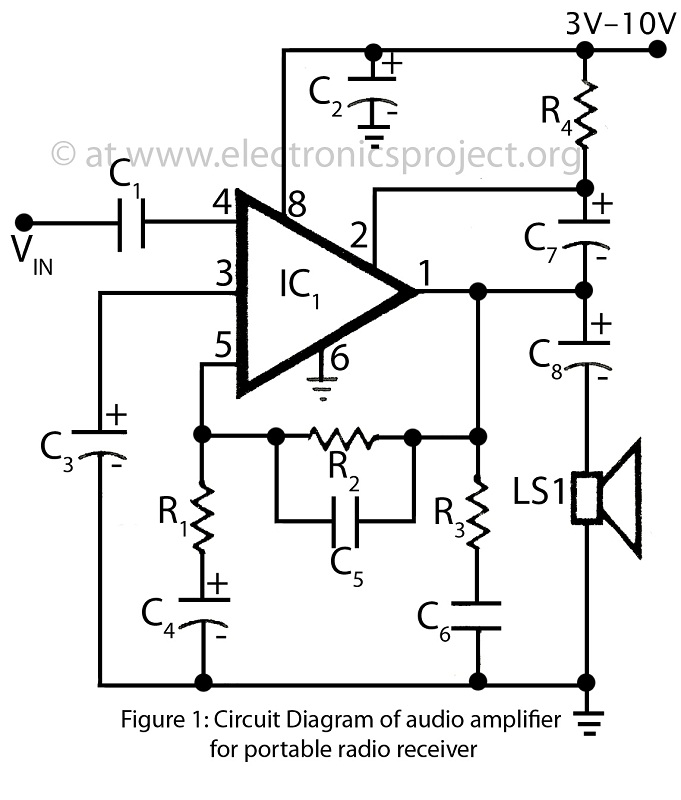
This is a simple audio amplifier circuit built around the BEL1895 1W audio amplifier integrated circuit (IC). This circuit serves as an alternative to more complex audio amplifier circuits designed for portable radio receivers. It does not require a...
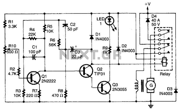
This regulator is designed to control a DC generator. In this configuration, one side of the field is grounded. Diode D4 prevents the battery from discharging through the generator and serves as a replacement for the mechanical cut-out relay....
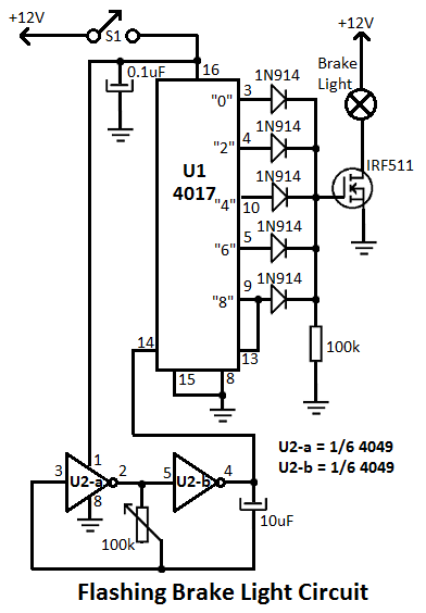
This flashing brake light circuit is designed for motorcycles. When the brake light switch S1 is closed, power is supplied to U1 and U2. The circuit utilizes two inverters from U2. The flashing brake light circuit operates by utilizing a...
The circuit topology is similar to the previously mentioned amplifier, utilizing the robust IRFP240 and IRFP9240 MOSFET devices as the output pair, along with high-voltage Motorola transistors in the preceding stages. The supply rail voltage is conservatively set at...
This simple circuit can be used to protect a bike from theft. It produces a loud alarm tone if someone attempts to start the bike. The alarm can only be disabled when the hidden switch S2 is opened. The...
The amplifier drives a pair of loudspeakers using two LM3876 integrated power amp ICs (50 watts per channel), or a pair of headphones via a Meier crossfeed filter and an OPA2134 dual opamp. It provides four switchable line level...