
iPod/MP3 Mini Speaker System
The amplifier in this system amplifies electrical signals, making them stronger and louder. It enables the use of higher resistance speakers by boosting the audio signal. This solid-state, high-gain amplifier design is intended for use with an 8-ohm speaker and was originally designed by Ed Vogel and Blind Lightnin' Pete from MAKE Magazine.
Before assembling the circuit, it is crucial to understand the layout of the protoboard. The board consists of four columns, with the outer two columns connected in rows and the inner two columns also connected in rows. Care must be taken to ensure that the IC DIP socket is positioned correctly, with its pins aligned with the columns to avoid incorrect connections that could prevent the circuit from functioning.
To facilitate assembly, it is recommended to build the circuit pin by pin, starting with pin 2 of the IC DIP socket, followed by the subsequent pins. Organizing the circuit can simplify the construction process; labeling the outer columns of the last two rows as negative and the inner columns as positive can streamline connections to the battery. The positive terminal can be connected to the designated area for +9V, while the negative terminal can be connected to the area designated for ground.
Attention should be given to the output lead connected to pin 5 of the circuit and to the switch connected to pin 6. The switch completes or disconnects the circuit and should not be soldered until later assembly into the enclosure. Once the amplifier circuit is constructed and connected to an 8-ohm speaker, sound playback can commence.
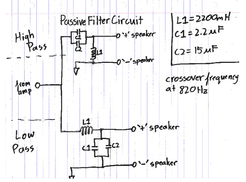
To enhance sound quality, incorporating a filter circuit can be beneficial. A filter circuit, also referred to as a crossover, divides the audio signal into different frequency ranges, allowing the speaker to handle a narrower range of frequencies more efficiently. This results in improved audio clarity and performance.
In summary, the mini speaker system project serves as an educational platform for understanding basic electronic circuits, with practical applications in music playback. It combines an amplifier and filter circuit in a user-friendly design, making it accessible for beginners and electronics enthusiasts alike.Listen and share your music wherever you go With the mini speaker system project, you can listen to music whenever you want: your dorm, your cubicle, or at the beach. This is a great introduction to circuit systems, featuring an introductory amplifier circuit, a filter circuit, and a simple enclosure.
When you`re done, all you need to do is add a 9V battery, plug in and play! The Amplifier In audio terms an amplifier does exactly what its name suggests: it amplifies the current. That is, it takes an electrical signal and makes the signal stronger, and in the end, louder. An electrical signal that is passed by an amplifier comes out louder through the speaker than one that hasn`t been amplified.
Also, because the signal is strengthened by an amplifier, you can play that music through higher resistant speakers. This amplifier is a solid-state-hi-gain design and is intended to run through an 8 ohm speaker. As the amplifier schematic was originally designed by Ed Vogel & Blind Lightnin` Pete from MAKE Magazine, all credit goes to them for the amplifier design.
Before we begin to build the circuit for the amplifier, let`s take a look at the protoboard. This board has a specific layout that should be understood before beginning to solder (unless you enjoy desoldering). The topology of this board is such that there are four columns in which the outer two columns are connected in rows, and the inner two columns are connected in rows.
This should be taken into account when building the circuit. Place solder on the IC DIP socket in a way that none of the rows are connecting. This means that you need to place the IC DIP socket so that the pins are parallel with the columns and the IC DIP socket crosses the gap between one of the outer and inner rows. Also note at which end pin 1 will be located. If you don`t do this your circuit may not work, due to putting the op amp in backwards. Begin to build the circuit as described in the schematic. One trick I found particularly helpful was to make the circuit pin by pin. That is, I worked on the circuitry connected to pin 2 of the IC DIP socket, and then pin 3 and 4 then 5 etc.
Before I began constructing the rest of the circuit, I wanted to do some organization to make the rest of the circuit much easier. I labeled the outer columns of the last two rows (and soldered them together) as negative and the inner columns of the last two rows as positive.
Then I attached the corresponding battery leads to these areas. This way, whenever something needs to be connected to +9V I will hook it up to the `+` area and whenever something needs to be connected to -9V (including anything that needs to be grounded as the -9V will serve as a ground in this circuit), it will simply be hooked up to the `-` area. This method of organization works well for me, you may have another way that works too! Work on pin 5 of the circuit. The wire that is coming from the circuit is the output lead. Also important to note is that it is connected to the center pin of the rheostat. Work on pin 6 of the circuit. It is important to note that the switch is connected to the `+` area and the other to the `+` end of the capacitor.
The end doesn`t particularly matter because a switch merely completes/disconnects a circuit. For now, don`t solder the leads to the switch, as you will need to screw them into the box later. What I did was tie the wire to each end of the switch so that I can remove them later. At this point, we`ve constructed an amplifier circuit. If we hook up an 8 © speaker, we can blast some awesome tunes through it. However, we could do better One way to increase the quality of sound through a speaker system is by utilizing a filter circuit. A filter circuit (also known as a crossover) basically splits up a signal into ranges of frequencies.
This way a speaker would only have to play a smaller range of frequencie 🔗 External reference
Related Circuits
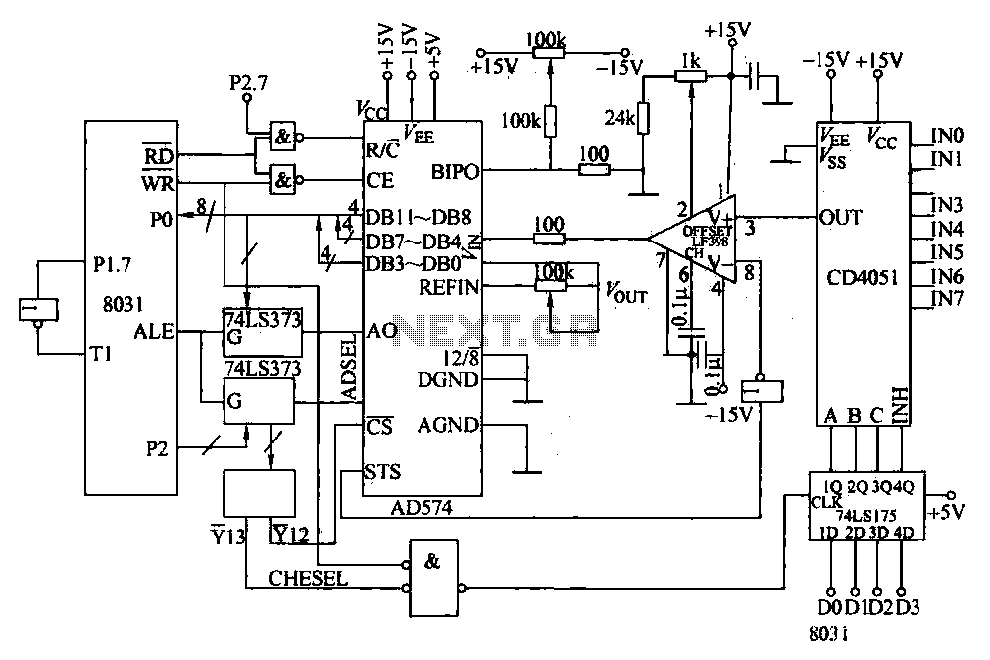
Converters and data sampling: A 12-bit A/D converter, AD574, is interfaced with an 8031 microcontroller circuit. Parameters are measured by a multi-way switch after a CD4051 strobe signal is sent to the sample/hold input device. The selection of the...
The momentary switch utilized has a safety rating of 10A. If a switch is rated for a current that is too low, the instantaneous current during the first millisecond could cause the switch contacts to fuse together. To achieve...
The circuit utilizes the functions of reed switches to create a gate alarm powered by a universal AC/DC power supply oscillator. The circuit operates by integrating reed switches, which are sensitive to magnetic fields, into an alarm system designed to...

This amplifier was designed to be self-contained in a small loudspeaker box. It can be fed by Walkman, Mini-Disc, iPod, CD players, computers, and similar devices fitted with line or headphone output. Of course, in most cases, you will...
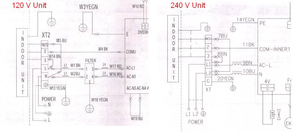
If the gears are switched over 5,000 during a solar eclipse, the nut bearings will need to be revalved. There are many factors involved in this process, similar to making a sandwich. The units in question are Fedders Inverter...
Construct a two-color camera and a three-color monitor. The camera can be designed to capture any two of the additive primary colors by placing the appropriate color filters over phototransistors or photodiodes. A matrix circuit and an inverter will...