
Ipod stereo 1W FM transmitter
The schematic shows an RF amplifier with very high gain. The feeding RF signal enters C9 to transistor Q1, which has a self-biased working point. The gain and working point are set with the two resistors R1 and R2. FB1, C5, and C6 work as filters for rejecting RF to the power line. Q1 has a gain of about 15 dBm. The output signal can be found at the collector, which then enters a second amplifier stage Q2. This stage also has a self-biased working point. The gain is set by resistors R3//R4 and R5//R6. The use of parallel resistors allows for gain adjustment; when two resistors are soldered on top of each other, it provides flexibility in gain selection.
It is advisable to start building without R3 and R5 to test the unit initially. If desired, R3 and R5 can be added later to achieve maximum gain for this stage. Q2 has a gain of 12 dBm. FB2, C7, and C8 serve as filters for rejecting RF to the power line.
The final amplifier stage is based around the transistor 2N3866, which has low input impedance. To match this, two capacitors (C11, C12) and an inductor (L1) are used to achieve an approximate impedance of 50 ohms. The transistor's output impedance is matched using capacitors (C13, C14) and inductor L3 to optimize performance for a 50-75 ohm antenna.
The inductors are constructed with specified turns and diameters: L1 with 2 turns and 5 mm diameter, L2 with 7-9 turns and 6.5 mm diameter, and L3 with 4 turns and 6.5 mm diameter. Capacitors C11 to C14 must be tuned for optimal performance.
A simple testing method for the amplifier involves building an additional dipole antenna to serve as a receiver. The dipole antenna receives the signal, which is then rectified to a DC voltage by a germanium diode and a 10 nF capacitor. A 100 µA meter can be used to display the signal strength. The 100k resistor and operational amplifier can be removed for a direct connection to the uA meter, although this will reduce sensitivity.
To tune the system, the receiving antenna should be placed a distance away from the transmitting antenna, adjusting capacitors C11 to C14 until the maximum reading is achieved on the 100 µA meter. If the reading is too strong, a series resistor can be added to the uA meter, or the meter can be moved further away. For low signals, the operational amplifier can be utilized with a 10k potentiometer for gain adjustment. Additionally, an MSA-0636 Cascadable Silicon Bipolar MMIC Amplifier can be integrated between the antenna and the rectifier for improved performance.
While tuning can also be conducted using a dummy load or wattmeter, tuning with the actual antenna connected is preferred to measure real field strength. L4 serves as an axial lead bead that effectively rejects RF while maintaining low resistance. This component is not critical, allowing for various choke or large inductor options.
The FM transmitter operates on 2 AAA batteries, consuming approximately 38 mA. To eliminate battery dependency, a voltage regulator (IC1) has been incorporated into the PCB, providing a stable 3.3V supply for the FM transmitter unit.The transmitting signal can the be picked up by any FM radio receiver. Most often used in cars. The problem with most FM transmitter is that they have very weak signal and short transmitting range. Some units are so bad that even when they are placed really close to the receiver, you barely receive the signal.
Stereo transmits on FM channels 87.5 MHz-108.0M Hz (0.1MHz increments). Distorsion < 3%. Signalto noise > 45dB. Memorize up to 4 FM frequencies. Features low-battery LED indicator. Operating Range: 20-40 feet. (Requires 2 AAA batteries (38mA)).Audio Frequency Range: 20Hz to 20Khz. Low battery detect function. Temperature guage. LCD clock display. Blue display light. The schematic show you a RF amplifier with very high gain. The feeding RF signal enter C9 to transistor Q1 which has a self biased working point. The gain and working point is set with the two resistors R1 and R2. FB1, C5, C6 works as filter for rejecting RF to power line. Q1 has a gain about 15dBm. The output signal can be found a the collector which then enter a second amplifier stage Q2. This stage also has a self biased working point. The gain is set by the resistors R3//R4 and R5//R6. Why do I have 2 parallel resistors like that? It is because I want to be able to change the gain of the amplifier. On the PCB below you will see that I only have 2 pads for the resistors. When I want to resistors I solder the two resistors R5 and R6 on top of each other and the same with R3 and R4. I advice you to start building without R3 and R5 and test the unit. If you want you can then add R3 and R5 later to obtain max gain of this stage. Q2 has a gain of 12 dBm. FB2, C7, C8 works as filter for rejecting RF to power line. The last amplifier stage is based around the transistor 2N3866. This transistor has low input impedance. I match it by using 2 capacitors (C11, C12) and the inductor L1 to about 50 ohm. The transistor has an output impedance match, (C13, C14, and L3) to get best performance for an 50-75 ohm antenna.
The inductor L1 is made by a wire 2 turns with 5mm diameter. The inductor L2 is made by a wire 7-9 turns with 6.5mm diameter. The inductor L3 is made by a wire 4 turns with 6.5mm diameter. There is four capacitors C11 to C14 you have to tune for best performance. A simple way to test the amplifier is to build an extra dipole antenna and use it as a receiver. Take a look at the schematic at right. I use a dipole antenna as receiving antenna and the signal is then rectified to a DC voltage by the germanium diode and the 10nF cap. An 100uA -meter will then show the signal strength. A very easy unit to build. You can remove the 100k resistor and the OP, and connect the uA meter directly after the diode. The unit will not be so sensitive then, but still work good. I place the receiving antenna a bit away from the transmitting antenna and tune (C11 to C14) until I reach strongest reading from the 100uA meter.
If you get too strong reading you can add a serial resistor to the uA meter or move it farther away. If you get to low signal you can use the OP and set high gain with the 10k pot. You can also add a (MSA-0636 Cascadable Silicon Bipolar MMIC Amplifiers) between the antenna and the rectifier. Of course you can tune your system with a dummy load or wattmeter, but I prefer to tune my system with the real antenna connected.
In that way I tune the power amplifier and measure the real field strength with my second antenna. L4 is a Axial Lead Bead, which reject RF very good and has low resistance. You can use almost any choke or large inductor for L4, it is not a critical component. The FM transmitter require 2 AAA batteries and consume about 38mA. To get rid of batteries, I have added a voltage regulator IC1, to the PCB which deliver 3.3V to the FM transmitter unit. 🔗 External reference
Related Circuits
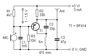
The presented FM transmitter circuit is constructed using BF414, BF324, or BF606 transistors. It features a 30 cm antenna that provides a range of approximately 30 meters indoors and even greater range outdoors. The power supply consists of two...
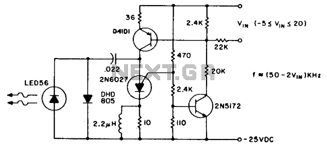
The pulse repetition rate is largely unaffected by temperature and power supply voltage, and it varies linearly with V1N, the modulating voltage. Effective information transfer was achieved at distances of 12 feet (~4m) in free air. A greater range...
In this circuit, a 74HC14 hex Schmitt trigger inverter is used as a square wave oscillator to drive a small signal transistor in a class C amplifier configuration. The oscillator frequency can be either fixed by a crystal or...
This 2-meter 144 MHz fox hunt transmitter is utilized in amateur competitions where participants seek to locate a concealed transmitter using primarily homebrewed receivers. The 144 MHz fox hunt transmitter is designed for use in amateur radio competitions, commonly referred...
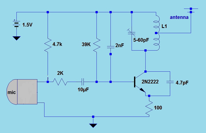
This simple FM (frequency modulation) transmitter is powered only by a 1.5V battery and utilizes a single transistor. The frequency of this transmitter is controlled by the L-C resonance circuit and operates within a range of 80 to 110...
This transmitters' intended purpose is for morse-code only in the 30 meter band (10Mhz). It is a low-power QRP type and needs to be connected to your existing tranceiver. The harmonic rejections on the prototype were measured at 40dB...
Warning: include(partials/cookie-banner.php): Failed to open stream: Permission denied in /var/www/html/nextgr/view-circuit.php on line 713
Warning: include(): Failed opening 'partials/cookie-banner.php' for inclusion (include_path='.:/usr/share/php') in /var/www/html/nextgr/view-circuit.php on line 713