
IR (Infrared) DetectorCircuit
The initial statement highlights a common dynamic in household technology usage, specifically focusing on the television remote control. In an electronic schematic context, this scenario can be expanded to illustrate a simplified remote control system and its components.
A typical television remote control operates using infrared (IR) or radio frequency (RF) signals. The remote consists of a microcontroller that processes user inputs. When a button is pressed, the microcontroller generates a specific binary code corresponding to the function requested, such as changing the channel or adjusting the volume.
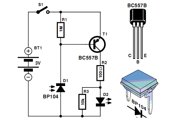
The output from the microcontroller is directed to an IR LED (light-emitting diode) in an IR-based remote control. The LED emits modulated infrared light, which is received by the television’s IR sensor. The sensor converts the IR light back into electrical signals, allowing the television to interpret the command.
In RF-based remote controls, the microcontroller sends signals to an RF transmitter, which broadcasts the command over radio waves. The television is equipped with an RF receiver that decodes the signals and executes the corresponding action.
Power for the remote control typically comes from batteries, which are connected to the microcontroller and the IR or RF transmitter. The circuit design includes components such as resistors, capacitors, and possibly a crystal oscillator to ensure stable operation and timing for the signals.
In summary, the schematic for a remote control system would include a microcontroller, an IR LED or RF transmitter, an appropriate power supply, and necessary passive components to ensure functionality and reliability. This design enables users, regardless of gender, to conveniently control their television experience, although it may lead to varying levels of satisfaction among partners.Men in particular enjoy the convenience of television remote controls often to the annoyance of their female partners. Men apparently want to know what.. 🔗 External reference
Related Circuits
The following circuit illustrates a Water Level Detector Circuit Diagram. This circuit is based on the PIC12F683 microcontroller. Features include the ability of the PIC microcontroller to enter a sleep mode. The Water Level Detector Circuit utilizing the PIC12F683 microcontroller...
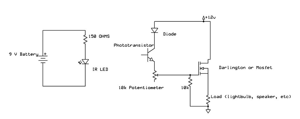
Recently, samples of IR LEDs and a corresponding IR phototransistor were acquired. A project was initiated to utilize these components. The project involves the integration of infrared (IR) LEDs with an IR phototransistor to create a simple optical communication system...
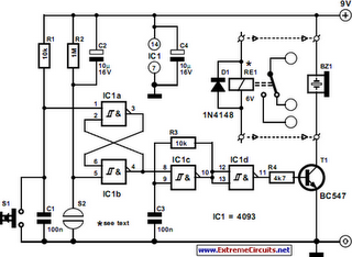
The following circuit illustrates a Simple Moisture Detector Circuit Diagram. This circuit is based on the 4093 IC. Features include the ability to detect a certain level of moisture. The Simple Moisture Detector Circuit utilizes the 4093 integrated circuit, which...
An infrared (IR) sensor or detector circuit diagram utilizing a 555 integrated circuit (IC), primarily employed as a water level or liquid level sensor and proximity detector circuit. The described circuit employs a 555 timer IC configured in a monostable...
Men particularly enjoy the convenience of television remote controls, often to the annoyance of their female partners. They tend to want to know what they are missing when the TV is tuned to a specific program, leading them to...