
Ir-receiver
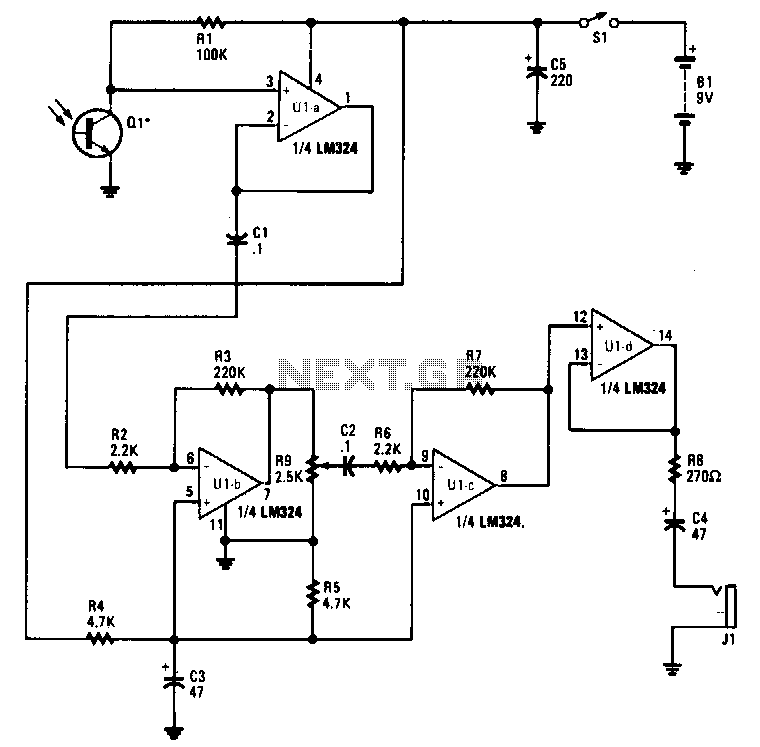
Infrared emissions detected by Q1 are transmitted through U1A to U1B, which amplifies the signal by a factor of 100. The amplified output of U1B is sent to U1C through R9, C2, and R6. Potentiometer R9 functions as a volume control. When R9 is adjusted to allow the maximum signal, U1C provides a gain of 100, resulting in a total system gain of 10,000 dB. The output of U1C is connected to a voltage follower circuit U1D to effectively match and drive headphones that can be connected to J1.
The circuit begins with the detection of infrared emissions by Q1, which acts as the sensor element. The signal from Q1 is routed to operational amplifier U1A, where initial signal conditioning occurs. Following this, U1B amplifies the signal significantly, achieving a gain of 100. This amplification stage is crucial for enhancing weak infrared signals to levels suitable for further processing.
The output of U1B is then connected to U1C, which is configured to provide additional amplification. The components R9 (a potentiometer), C2 (a capacitor), and R6 (a resistor) form a critical part of the signal path. R9, as a volume control, allows for user-adjustable gain, ensuring that the signal can be fine-tuned to the desired level. When R9 is set to pass the maximum signal, U1C achieves its full gain of 100, resulting in an overall system gain of 10,000 dB, which is substantial for audio applications.
The output from U1C is subsequently routed to U1D, which functions as a voltage follower. This configuration is essential for impedance matching, ensuring that the output can effectively drive headphones connected to jack J1. The voltage follower prevents loading on the previous stage while delivering the necessary current to headphones, thus maintaining audio fidelity and performance.
The design of this circuit highlights the importance of each component in achieving a high-gain amplification system suitable for infrared signal processing and audio output. The careful selection of operational amplifiers and passive components ensures optimal performance and adaptability for various headphone types.Infrared emissions detected by Ql are fed through Ula to Ulb, which amplifies the signal by a factor of 100. The amplified output ofUlb is fed to Ulc through R9, C2, and R6. Potentiometer R9 serves as a volume control. With R9 set to pass the maximum signal, Ulc provides a gain of 100, for a total system gain oflO,OOO dB.
The output ofUlcis connected to voltage follower circuit Uld to better match and drive headphones that can be plugged into J1. 🔗 External reference
Related Circuits
This Atmel integrated circuit operates at a clock frequency of 12 MHz, facilitating communication between an infrared receiver and a personal computer. This setup enables the processing of signals by infrared receiver software, such as Girder. When a valid...