
ir remote switch
The circuit design integrates several key components to ensure reliable operation and user convenience. The IR receiver module is sensitive to the specific frequency emitted by common remote controls, making it versatile for various applications. The NE555 timer is a widely used component in timing applications, and its monostable configuration is adept at providing a fixed output duration, which is crucial for preventing rapid toggling of the relay.
The inclusion of the J-K flip-flop introduces a binary state control, allowing the relay to be activated or deactivated based on the input from the monostable output. This feature is particularly useful for applications where momentary activation is required, such as turning on a light or fan without the need for continuous input from the remote.
The SL100 transistor serves as a switching device, amplifying the current from the flip-flop to drive the relay coil effectively. The back EMF protection diode is a critical component in relay circuits, safeguarding the transistor and other sensitive components from voltage spikes generated when the relay coil is de-energized.
The power supply, regulated by the 7805 voltage regulator, ensures that the circuit operates within safe voltage levels, providing stability to the entire system. Capacitors C5, C3, and resistor R3 are strategically placed to filter out noise and stabilize the operation, contributing to the overall reliability of the circuit.
This remote-controlled relay circuit is suitable for various applications in home automation, providing an easy and efficient way to control electrical devices from a distance. The design can be adapted for different voltage levels and types of devices, making it a flexible solution for remote switching needs.Imagine the convenience of selecting TV channels using your remote and then pointing the same remote to your switchboard to switch on/off the fan or the tubelight. Here is a simple circuit to remotely switch on/off any electrical device through a relay using the normal TV/VCR/VCP/VCD remote control unit.
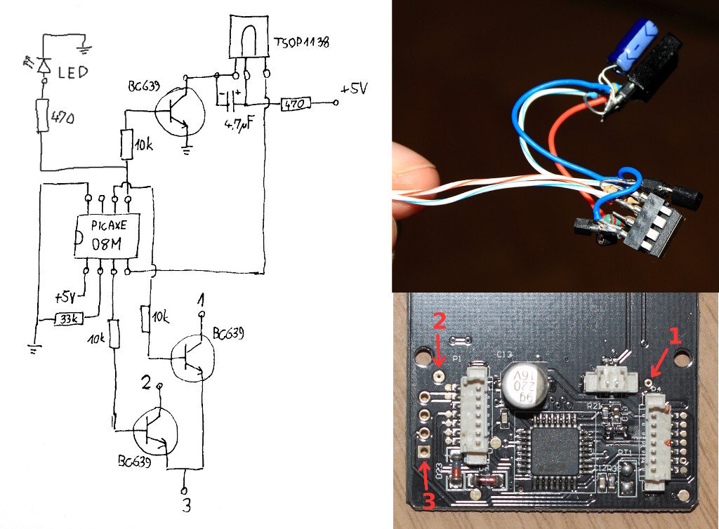
It works up to a distance of about 10 metre s. The circuit is built around a 3-pin IR IC receiver (Siemens SFH-506-38 or equivalent) that can detect 38kHz burst frequency generated by a TV remote. (This IR receiver module has been covered earlier in many projects published in this blog. ) The output pin of IR sensor goes low when it detects IR light, triggering the monostable (1-second) built around timer NE555.
The output of the mono toggles the J-K flip flop, whose Q output drives the relay through SL100 npn transistor (T1). LED2, LED3, and LED4 are used to display the status of each output stage during circuit operation. Back-EMF diode D5 is used for protection. Transistor T1 is configured as an open-collector output device to drive the relay rated at 12V DC. The circuit draws the power from voltage regulator 7805. Capacitor C5 is soldered close to the IR sensor`s pins to avoid noise and false triggering. Capacitor C3 and resistor R3 also avoid false triggering of monostable NE555. The monostable acts as a 1-second hysterisis unit to restrict the flip-flop from getting retriggered within one second.
To activate any other 12V logic device, use the output across the relay coil terminals. 🔗 External reference
Related Circuits

The sound captured by speaker SPKR1, functioning as a microphone, is transmitted to transistor amplifier Q1. The output from Q1 is connected to coupling transformer T1, which is utilized to activate the gate circuit of Triac TR1. Additionally, TR1...

A high voltage switching stabilized voltage supply circuit is illustrated in the diagram. This is the switching power supply for an 80P type color television. It utilizes auto-excitation and a PWM circuit. The output is isolated from the power...
The YN-460 is an affordable manual-only shoe mount flash produced by the Chinese company Yongnuo. It has gained popularity within the strobist community primarily due to its low price and satisfactory performance. To adjust the flash power level, users...

After searching for a few days, a solution for this idea has not been found. A switch panel is being created in the dashboard containing four switches. The switch panel design for the dashboard involves integrating four switches that can...

The Multiport W723 is an adjustable constant current regulator designed for use in switching regulator circuits, capable of delivering an output current of 1A. In the illustrated circuit, the W723 reference base voltage is approximately 7.2V. This voltage is...

These circuits allow an ON-ON type DPDT toggle switch to control a twin coil switch machine motor. The handle of the switch can then be used to indicate the route selected. The circuits are also able to control LEDs...