
IR Widget
This project is ideal for individuals interested in understanding infrared (IR) remote controls and their operation. The circuit, sourced from online resources, is straightforward and utilizes a programmable chip from Microchip. A comprehensive tutorial covering the entire project is not readily available, prompting an effort to document findings throughout the development process. The programming mode voltage must be connected to the MCLR pin of the target PIC microcontroller. To enter programming mode, this line must remain within a specific voltage range that varies among different PIC models but must always exceed Vdd. The maximum allowable Vpp voltage identified is 13.5 volts. There is no singular Vpp voltage that is universally valid for all PICs. Vdd serves as the positive power input to the PIC. Some programming devices necessitate this voltage to be supplied by the circuit (which must be partially powered), while others can provide it independently and require the circuit to be powered off. The Microchip ICD2, for example, can operate in either configuration. Conversely, Embed Inc programmers expect to supply the Vdd line themselves and require the target circuit to be powered off during programming. The negative power input to the PIC serves as the ground reference for other signals, with voltages of these signals referenced to GND unless stated otherwise. The serial data line operates in a bi-directional manner, allowing communication to be initiated by either the programmer or the PIC, with voltage levels oscillating between GND and Vdd. Data is transmitted on the falling edge of the PGC signal.
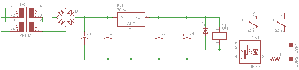
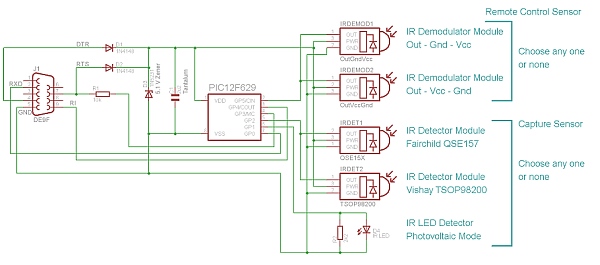
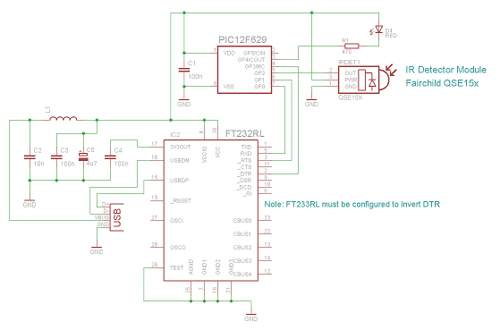
The described project centers around the design and implementation of an IR remote control system, leveraging a Microchip PIC microcontroller. The essential components of the circuit include the PIC microcontroller, a power supply configuration, and an IR transmitter and receiver module.
The PIC microcontroller is programmed to interpret signals from the IR receiver, which captures the modulated infrared light emitted by an IR remote control. The MCLR pin is crucial for entering programming mode, necessitating a specific voltage range to ensure the microcontroller is correctly set up for programming. The connection of the programming voltage (Vpp) to the MCLR pin must be carefully managed, ensuring it does not exceed the maximum limit of 13.5 volts.
For the power supply, Vdd is the main positive voltage input, while GND serves as the reference point for all other signals. The configuration of the power supply must be compatible with the requirements of the programmer being used. It is important to note that some programmers may require the circuit to be partially powered during the programming process, while others may function optimally with the circuit powered off.
The bi-directional serial data line is another critical aspect of the circuit, facilitating communication between the programmer and the microcontroller. The data transmission occurs on the falling edge of the PGC signal, which is essential for synchronizing the data exchange.
Overall, this project not only provides insights into the workings of IR remote controls but also illustrates the practical application of programming microcontrollers, emphasizing the importance of voltage management and signal integrity in electronic circuit design.Anyone who wants to understand IR remote controls and how they function, this project will be great for you. This circuit I found online seems so simple and uses my favorite programmable chip company (Microchip).
There really isn`t a FULL tutorial from start to finish on this project online. So I will attempt to fill in the gaps and po st my findings as I work through this project. - KC2NDA Programming mode voltage. This must be connected to the MCLR pin of the target PIC. To put the PIC into programming mode, this line must be in a specified range that varies between PICs, but is always above Vdd. The highest maximum allowed Vpp voltage that we know of is 13. 5 volts. There is no one Vpp voltage that is within the valid Vpp range of all PICs. This is the positive power input to the PIC. Some programmers require this to be provided by the circuit (circuit must be at least partially powered up), some programmers expect to drive this line themselves and require the circuit to be off, while others can be configured either way (like the Microchip ICD2).
The Embed Inc programmers expect to drive the Vdd line themselves and require the target circuit to be off during programming. Negative power input to the PIC and the ground reference for the remaining signals. Voltages of the other signals are implicitly with respect to GND unless otherwise specified. Serial data line. The serial interface is bi-directional, so this line can be driven by either the programmer or the PIC depending on the current operation.
In either case this line swings from GND to Vdd. A bit is transferred on the falling edge of PGC. 🔗 External reference
Related Circuits
Simple IR capture for multitasking operating systems. The IR Widget captures the infrared signals used by remote controls. It operates in a way that makes it suitable for multitasking environments. The IR Widget is designed to interface with multitasking operating...
The IR Widget operates in a manner that ensures compatibility with modern multitasking operating systems. It can determine the carrier frequency and demodulate the carrier in both the digital and analog domains. The captured information can be utilized to...