
Isolated-feedback-power-supply
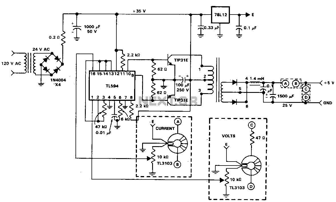
The diagram illustrates a power supply circuit that utilizes the isolated feedback capabilities of the TL3103 for current and voltage sensing. This supply is connected to the AC power line and delivers an output of 5 V at 1.5 A. Both the output voltage and current are monitored, and the resulting error voltages are fed into the error amplifiers of the TL594 PWM control IC. A 24-V transformer generates approximately 35 V at the 1000 µF filter capacitor. The switching frequency of 20 kHz is determined by a 6 kΩ resistor and a 0.01 µF capacitor connected to pins 6 and 5, respectively. The TL594 is configured for push-pull operation by setting pin 13 high. The 5-V reference at pin 14 is connected to pin 15, which serves as the reference for the current error amplifier. Additionally, the 5-V reference is linked to pin 2, which is the reference for the output voltage error amplifier. The output voltage and current limit are adjustable via 10 kΩ potentiometers in the TL3103 error-sensing circuits. A pair of TIP31E NPN transistors are employed as switching transistors in a push-pull configuration.
The power supply circuit described operates by converting AC voltage from the power line into a regulated DC output. The TL3103 plays a crucial role in sensing both the output voltage and current, ensuring that the power supply maintains stable operation under varying load conditions. The feedback mechanism allows for real-time adjustments based on the sensed values, which are processed by the TL594 PWM control IC. The TL594, in push-pull mode, alternates the operation of the TIP31E transistors to efficiently regulate the output.
The transformer steps down the voltage to a manageable level, while the filter capacitor smooths out the rectified output, providing a stable DC voltage. The choice of a 20 kHz switching frequency is significant for minimizing energy loss and optimizing performance, as it balances efficiency with the physical size of the components used. The error amplifiers within the TL594 are critical for maintaining the desired output voltage and current, as they compare the sensed values against the reference voltages and adjust the duty cycle of the PWM signal accordingly.
The use of adjustable potentiometers allows for fine-tuning of the output voltage and current limits, which is essential for applications requiring precise power delivery. The TIP31E transistors, being robust and capable of handling significant current, ensure that the circuit can deliver the required 1.5 A output without overheating or failing. This circuit design is suitable for a variety of applications where reliable power supply is essential, such as in embedded systems or industrial control systems.The diagram is a power supply circuit using the isolated feedback capabilities of the TL3103 for both current and voltage sensing. This supply is powered fromthe ac power line and has an output of 5 Vat 1.5 A. Both output voltage and current are sensed and the error voltages are applied to the error amplifiers of the TL594 PWM control !C.
The 24-V transformer produces about 35 Vat the 1000-I"F filter capacitor. The 20-kHz switching frequency is set by the 6-KO resistor and the 0.01-I"F capacitor on pins 6 and 5, respectively. The TL594 is set for push-pull operation by typing pin 13 high. The 5-V reference on pin 14 is tied to pin 15, which is the reference or the current error amplifier. The 5-V reference is also tied to pin 2 which is the reference for the output voltage error amplifier.
The output voltage and current limit are set by adjustment of the 10-KO pots in the TL3103 error-sensing circuits. A pair of TIP31E npn transistors are used as switching transistors in a push-pull circuit. 🔗 External reference