
Job Analysis push-pull output
The bootstrap capacitor is a critical component in various electronic circuits, particularly in enhancing the performance of switching converters and amplifiers. It operates by temporarily storing charge and providing a higher voltage to drive the gate of a high-side MOSFET in a half-bridge configuration. This allows the MOSFET to turn on fully, enabling efficient switching and reducing power losses.
In a typical configuration, the bootstrap capacitor C is connected between the supply voltage (V) and the gate of the high-side MOSFET. When the low-side MOSFET is turned on, the voltage at point B drops to ground potential, allowing the capacitor to charge up to the supply voltage. Once the low-side MOSFET turns off and the high-side MOSFET is activated, the charge stored in the bootstrap capacitor raises the gate voltage above the supply voltage, ensuring that the high-side MOSFET is fully enhanced for optimal conduction.
The performance of the bootstrap capacitor is influenced by its capacitance value and the load conditions. A larger capacitance can provide a more stable voltage during operation, especially in applications with rapid switching or variable load conditions. However, it is essential to ensure that the capacitor does not exceed its voltage rating, as this could lead to failure or reduced reliability in the circuit.
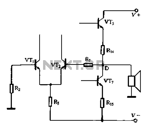
In summary, the bootstrap capacitor is integral to achieving high efficiency in power management systems, allowing for effective control of high-side switches in various applications, including motor drives, power converters, and other electronic systems requiring precise voltage regulation and control.A, B, c became indirect person capacitance Figure l-230 new access capacitor C is called the bootstrap capacitor. Self bootstrap capacitor can increase the voltage at point A. When static, Vi- oV, the midpoint voltage VD V +/2, B-point voltage VB VD V +/2, A point voltage hoot v + a VR, the bootstrap capacitor c is A, is charged between B, charging voltage V VA - VB v bucket. A VR + -V/2 v +/VR 2, VR is negligibly small due. When C is large, even if the AC signal voltage by too, the charge voltage V +/2 does not change.
Related Circuits
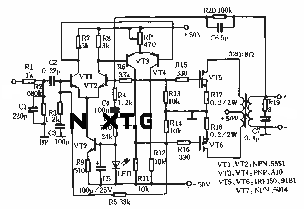
This article describes a transformer-based output FET amplifier, with tonal characteristics similar to those of tube amplifiers. It introduces various effects that are significant for audio enthusiasts. Power amplifier specifications include a rated output power of 50W (with an...
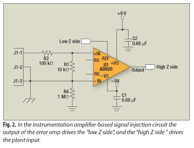
A signal-injection circuit for control-loop analysis is flat from DC to 200 kHz, isolated from chassis ground, and easily constructed with a readily available instrumentation amplifier. The signal-injection circuit is designed to facilitate control-loop analysis by providing a stable and...
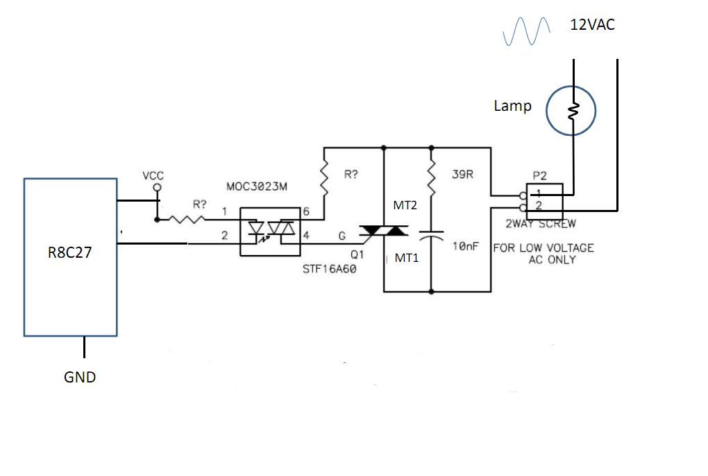
Control 30 incandescent light bulbs with an Arduino Uno on three channels (10 bulbs per channel in parallel). Previous experience involved using an Arduino to control red, green, and blue LEDs with a simple schematic that included three transistors....
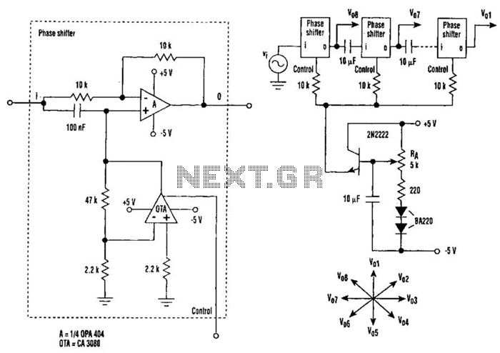
The circuit consists of eight cascaded identical cells, each cell being a DC-controlled active phase shifter. Since the DC control is common for all shifters, the circuit is adjusted by tuning resistor RA so that the phase difference between...
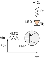
The PNP transistor is the exact opposite of the NPN transistor discussed in the previous tutorial. In this type of transistor construction, the two diodes are reversed compared to the NPN type, resulting in a Positive-Negative-Positive configuration, with the...
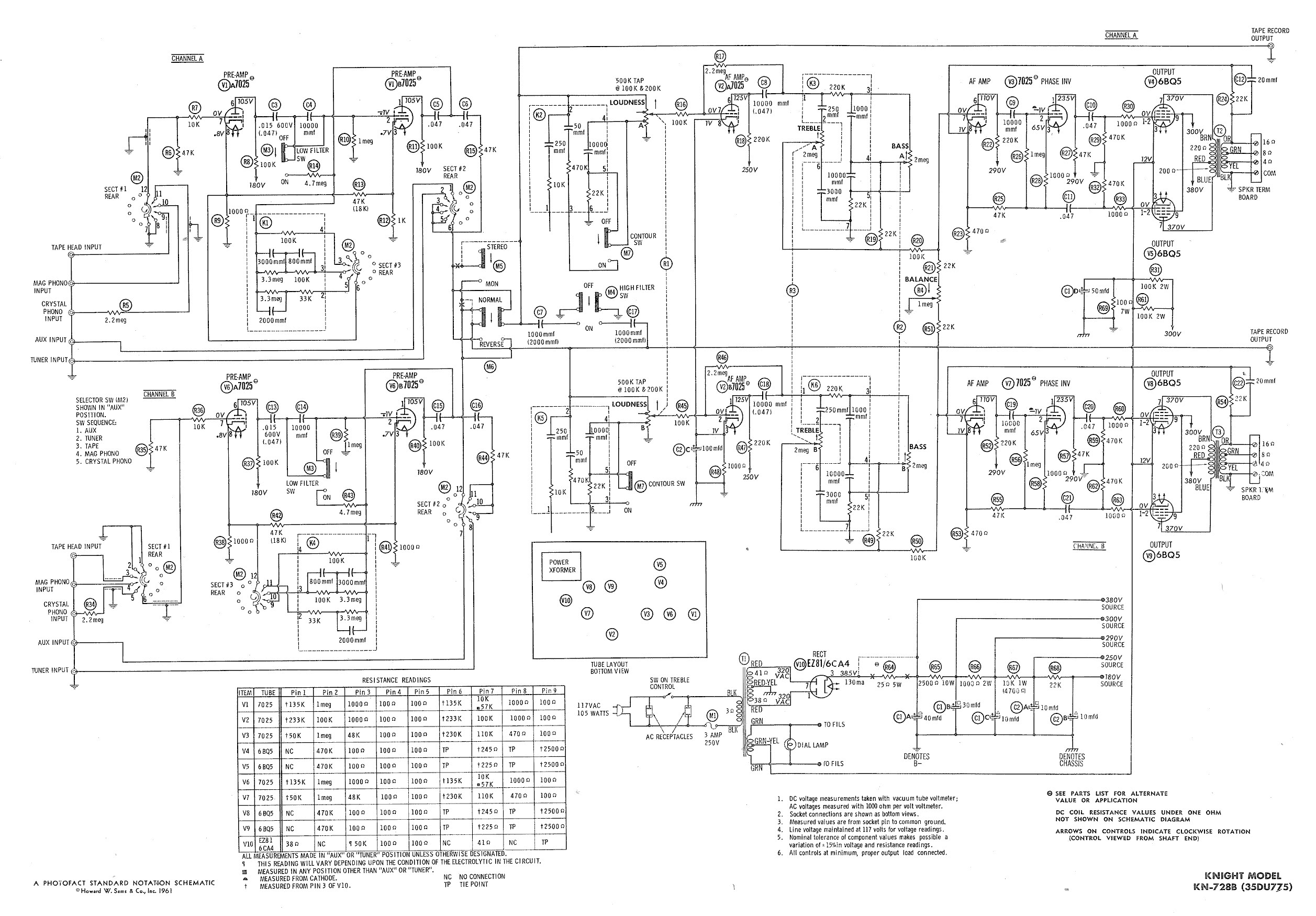
Ty - Concerning the updated schematic of the AF/PI stage, it appears that resistor R45 is not present. Additionally, the disk capacitor bypassing R44 is marked as 68nF750 with a tolerance of 10%, which is presumed to be the...