
Jogging Timers

The circuit utilizes a single-pole, nine-way rotary switch (SW1) to select the desired timing interval for the piezo sounder. Each position on the switch corresponds to a specific time delay, allowing the user to choose between one and nine minutes. The timing mechanism can be implemented using a combination of resistors, capacitors, and a timer IC, such as the 555 timer, configured in astable or monostable mode depending on the desired functionality.
In the astable configuration, the timer can continuously generate a square wave output, which can be adjusted by changing the resistor and capacitor values to set the beep interval. If a monostable configuration is preferred, the timer can be triggered by the rotary switch, and it will generate a single output pulse that corresponds to the selected time interval. The piezo sounder then emits a series of beeps, with the frequency and duration of the beeps being determined by the output from the timer circuit.
To enhance usability, a simple LED indicator can be added to visually confirm the selected position of the rotary switch. The circuit can be powered by a standard battery or DC power supply, ensuring portability for jogging or outdoor activities. Overall, this timer circuit serves as a practical solution for users looking to maintain a specific jogging pace with audible feedback.This circuit was developed since a number of visitors of this website requested a timer capable of emitting a beep after one, two, three minutes and so on, for jogging purposes. As shown in the Circuit diagram, SW1 is a 1 pole 9 ways Rotary Switch. Setting the switch in position 1, the Piezo sounder emits three short beeps every minute. In positio n 2 the same thing happens after 2 minutes, and so on, reaching a maximum interval of 9 minutes in position 9. 🔗 External reference
Related Circuits

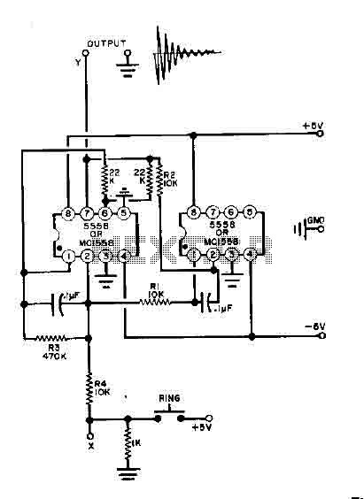
The following method allows the timer to be triggered by a normally closed switch. This would be useful in applications such as intrusion alarms where the protection circuit is broken if a window or door is opened. Trigger Input...
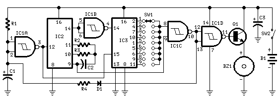
This circuit was developed in response to requests from visitors for a timer that can emit a beep after intervals of one, two, three minutes, and so forth, suitable for jogging purposes. As illustrated in the circuit diagram, SW1...
This simple bell circuit utilizes two 555 timers. The frequency is regulated by capacitors that should maintain nearly identical values for optimal performance. Fine-tuning is achieved using resistors R1 and R2. Additionally, the decay time is managed by resistor...
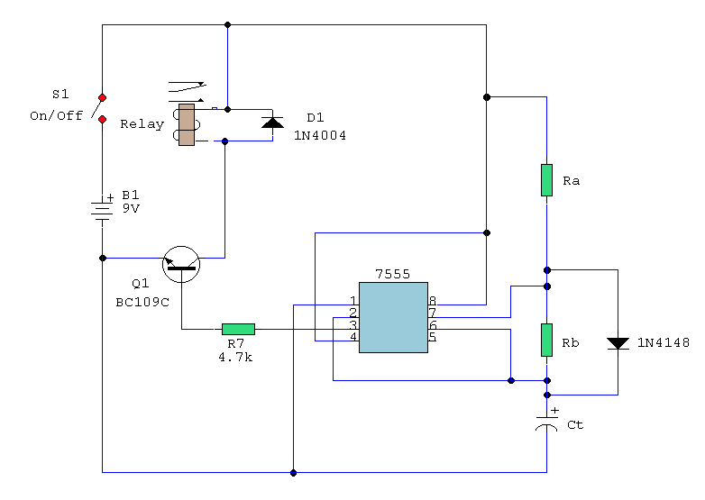
A simple astable timer made with the 555 timer IC allows independent adjustment of the mark (on) and space (off) values. The timing circuit comprises resistors Ra, Rb, and capacitor Ct. The capacitor Ct charges through resistor Ra, which...
The objective of this circuit is to power a lamp or other device for a predetermined duration (30 minutes in this instance) and subsequently turn it off. This functionality is particularly beneficial for reading in bed at night, as...
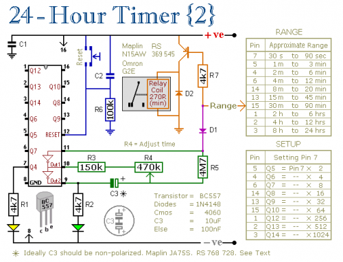
A pair of multi-range timers that provide timing periods of up to 24 hours and beyond. Both timers are fundamentally similar, with the primary distinction being that Version 1 energizes the relay when the time expires, while Version 2...
Warning: include(partials/cookie-banner.php): Failed to open stream: Permission denied in /var/www/html/nextgr/view-circuit.php on line 713
Warning: include(): Failed opening 'partials/cookie-banner.php' for inclusion (include_path='.:/usr/share/php') in /var/www/html/nextgr/view-circuit.php on line 713