
keypad floating voltages
A comprehensive understanding of the keypad lock circuit design involves several key components and their interactions. The passive keypad is configured as a matrix, where pressing a key connects a specific row and column, allowing the microcontroller to detect which key has been pressed. The 4 input pins from the keypad are connected to the microcontroller's GPIO pins, while the 4 output pins are used to activate specific rows based on the input selection.
To resolve the issue of floating voltages at the input pins, it is essential to implement pull-up resistors. These resistors should be connected from each input pin to the +5V rail. This ensures that when no key is pressed, the input pins are held at a high logic level (5V), preventing erratic behavior in the microcontroller. The recommended resistor values of 3.3K to 10K provide a balance between power consumption and effective pull-up strength.
When a key is pressed, the corresponding output pin is activated, and the row pin is pulled low, allowing the microcontroller to read a low signal on the input pin. This process is repeated for each row, enabling the detection of multiple key presses in sequence. The programming logic within the PIC microcontroller must accommodate the fact that when a column is set to high, the corresponding row pin will also be high if no key is pressed. This requires careful programming to ensure that the microcontroller accurately interprets the key presses without false triggering due to floating voltages.
In addition to the external pull-up resistors, if the microcontroller supports weak internal pull-ups, enabling these can further stabilize the input pins. This feature can be particularly useful in applications where external components are limited or where space constraints exist. The internal pull-ups typically provide a higher resistance (around 50K), which helps to reduce power consumption while still maintaining a reliable high state on the input pins.
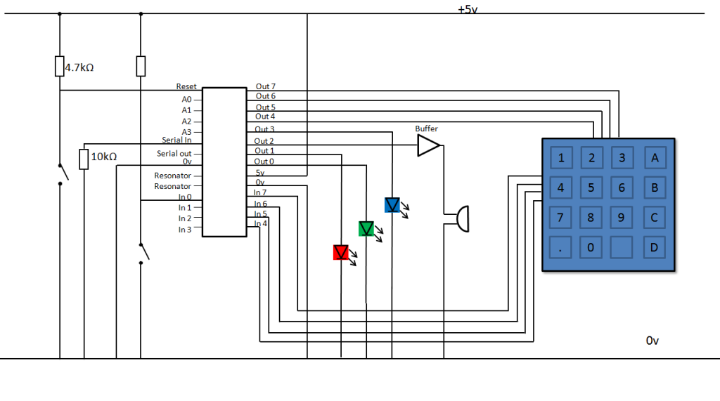
In summary, careful consideration must be given to the design of the keypad lock circuit, focusing on the configuration of the input and output pins, the implementation of pull-up resistors, and the programming logic within the PIC microcontroller. These elements are crucial for ensuring reliable operation and preventing issues related to floating voltages.Hey everyone. I am building a keypad lock for a project using a PIC and one of those passive keypa with 8 pins, 4 input 4 output. Each of the pins corresponds to a row of numbers on the 4 by 4 keypad, and the 4 output pins correspond to the numbers in that row.
so putting a 1 into input pin 1 will make the 4 output pins correspond to 1, 4, 7, dot. Putt ing a 1 into input pin 2 now makes 4 output pins correspond to 2, 5, 8, 0 etc. this then goes into the pic and that advances the programme etc. The problem is, the keypad keeps advancing the program without you pressing a key, the voltage into the pic floats around 1-2. 5v which I can`t get rid of. I have tried putting it through a 4050 non inverting buffer but then the output of the buffer just floats too.
it should be giving out a solid 0v or 5v, not 2. 5v I`m not sure what you mean by the weak internal pull ups, the keypad is all inside a plastic housing, so I can`t get to it, but I`m pretty sure it`s just a PCB. On the pins of the Picaxe that are used as inputs from the keypad, you need to have on each of the 4 pins a resistor from the pin to the +5V supply.
The value of the resistors can be from approx 3. 3K thru 10K, these will stop the pins from `floating`. The pins are not in anyway connected to the 5v rail though, I`m not sure how to add that in, the only power the keypad recieves are the 5v signals from the PIC For a Column that has been set to 5V by the program, will, if a key on that Column is closed, then Row pin will be pulled to +5V, which the program detects as a `1`. Note: In some cases depending upon the sense the Column is set active, it could be that the unselected Cols are all high and the selected Col is pulled low.
On many of the `larger` PIC`s on PORTB, there is an option in the configuration part of the program to enable `weak` INTERNAL pullup resistors [IIRC about 50k. ]. 🔗 External reference
Related Circuits
An 18-year-old electrical engineering student, Chris Rieger, has been developing his levitating light bulb project, aptly named the LevLight Project, for approximately six months. Recently, he shared images and a video of the project, which gained significant attention on...
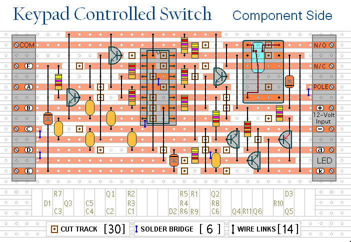
This is a universal version of the four-digit alarm control keypad. The design has been modified to free up the relay contacts, enabling the circuit to function as a general-purpose switch. A single pole changeover (SPCO) or single pole...
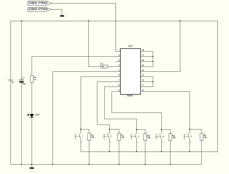
This project can be used for many different purposes. Probably the most used application would be to interface to any electronic project that requires a keypad. There are several ready made keypads on the market, but those work with...
This simple circuit is the electronic version of the combination lock. Using the special purpose LS7220 digital lock IC, the circuit allows a 4 digit combination of your choice to activate a relay for a set period of time....
This switch is designed for the Modular Burglar Alarm circuit but can be utilized in various other applications. The keypad must feature a common terminal with separate connections for each key. For a 12-key pad, there should be 13...

Speaker relay delay controlling circuit for audio amplifier The speaker relay delay controlling circuit is designed to manage the connection between an audio amplifier and the connected speakers, ensuring that the speakers are activated only after a predetermined delay. This...