
Km Counter / meter circuit
This circuit is designed to measure the distance traveled during walking, utilizing a compact hardware assembly that fits into a pocket. The distance measurement is displayed through two common-cathode 7-segment LED displays (D1 and D2). Display D2 indicates kilometers (Km) with a constant dot to demarcate it from hectometers (hm), while display D1 represents the hundreds of meters, illuminating its dot after every 50 meters walked.
The operation of the circuit is predicated on the detection of steps via a mercury switch (SW1), which is sensitive to tilting. Each normal step, approximated at 78 centimeters, activates the switch, allowing the circuit to count. Specifically, 64 steps (or 32 activations of the mercury switch) trigger the display to indicate 50 meters, while 128 steps correspond to 100 meters. To conserve battery life, the displays only activate when the display pushbutton (P2) is pressed.
To prevent accidental resets of the counters, both pushbuttons (P1 for reset and P2 for display) must be pressed simultaneously. The design does not prioritize precision but achieves a satisfactory level of accuracy suitable for casual distance tracking. The placement and angle of the mercury switch are crucial for reliable operation.
The circuit includes several resistors (R1 to R9) for biasing and signal conditioning, capacitors (C1 to C4) for filtering and decoupling, and integrated circuits (IC1 to IC4) for logic operations and counting. The 4093 IC acts as a quad 2-input Schmitt NAND gate to manage signal integrity, while the 4024 and 4026 ICs serve as ripple and decade counters to process the step counts and drive the displays.
Transistors Q1 and Q2 (BC327) are employed for driving the piezo sounder (BZ) and controlling the display logic. The sounder provides audible feedback at each counting unit, which can be disabled via a switch (SW2). Power is supplied by a 3V battery configuration using two AA cells in series.
The circuit's design demonstrates a practical approach to distance measurement, balancing simplicity with functionality, suitable for wearable applications.This circuit measures the distance covered during a walk. Hardware is located in a small box slipped in pants' pocket and the display is conceived in the following manner: the leftmost display D2 (the most significant digit) shows 0 to 9 Km. and its dot is always on to separate Km. from hm. The rightmost display D1 (the least significant digit) shows hundreds meters and its dot lights after every 50 meters of walking.
A beeper (excludable), signals each count unit, which occurs every two steps. A normal step is calculated to span approx. 78 centimeters, thus the LED signaling 50 meters lights after 64 steps or 32 mercury switch's operations, the display indicates 100 meters after 128 steps and so on. For low battery consumption the display lights only on request, pushing P2. Accidental reset of the counters is avoided because to reset the circuit both pushbuttons must be operated together. Obviously this is not a precision meter, but its approximation's degree was found good for this kind of device.
In any case, the most critical thing to do is placement and sloping degree of the mercury switch inside the box. R1,R3____22K 1/4W Resistor R2________2M2 1/4W Resistor R4________1M 1/4W Resistor R5,R7,R8__4K7 1/4W Resistor R6_______47R 1/4W Resistor R9________1K 1/4W Resistor C1_______47nF 63V Polyester Capacitor C2______100nF 63V Polyester Capacitor C3_______10nF 63V Polyester Capacitor C4_______10µF 25V Electrolytic Capacitor D1_______Common-cathode 7-segment LED mini-display (Hundreds meters) D2_______Common-cathode 7-segment LED mini-display (Kilometers) IC1______4093 Quad 2 input Schmitt NAND Gate IC IC2______4024 7 stage ripple counter IC IC3,IC4__4026 Decade counter with decoded 7-segment display outputs IC Q1,Q2___BC327 45V 800mA PNP Transistors P1_______SPST Pushbutton (Reset) P2_______SPST Pushbutton (Display) SW1______SPST Mercury Switch, called also Tilt Switch SW2______SPST Slider Switch (Sound on-off) SW3______SPST Slider Switch (Power on-off) BZ_______Piezo sounder B1_______3V Battery (2 AA 1.5V Cells in series) IC1A & IC1B form a monostable multivibrator providing some degree of freedom from excessive bouncing of the mercury switch.
Therefore a clean square pulse enters IC2 that divide by 64. Q2 lights the dot of D1 every 32 pulses counted by IC2. IC3 & IC4 divide by 10 each and drive the displays. P1 resets the counters and P2 enables the displays. IC1C generates an audio frequency square wave that is enabled for a short time at each monostable count. Q1 drives the piezo sounder and SW2 let you disable the beep. 🔗 External reference
Related Circuits
This device can also be referred to as an economical hearing aid, as it can be constructed using low-cost components. Although its performance does not match that of advanced commercially available hearing aids, it can effectively assist individuals with...
This FM spy telephone circuit is connected in series with the phone line. When there is a signal on the wires, this transmitter will radiate airwaves through the wires. This FM spy telephone circuit operates by integrating with the existing...
Several RS232 transceiver circuits are used for communication between microcontrollers and other devices, such as PCs or RS232 devices. This document presents a collection of well-known RS232 transceiver circuits. The circuit utilizes the MAX232 from Maxim's devices, which is...
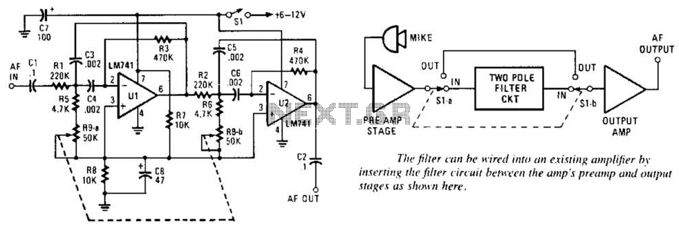
This variable-frequency audio bandpass filter is constructed using two 741 operational amplifiers (op amps) connected in cascade. Both op amps are configured as identical RC active filters, enhancing the selectivity of the overall circuit. The filter has a tuning...
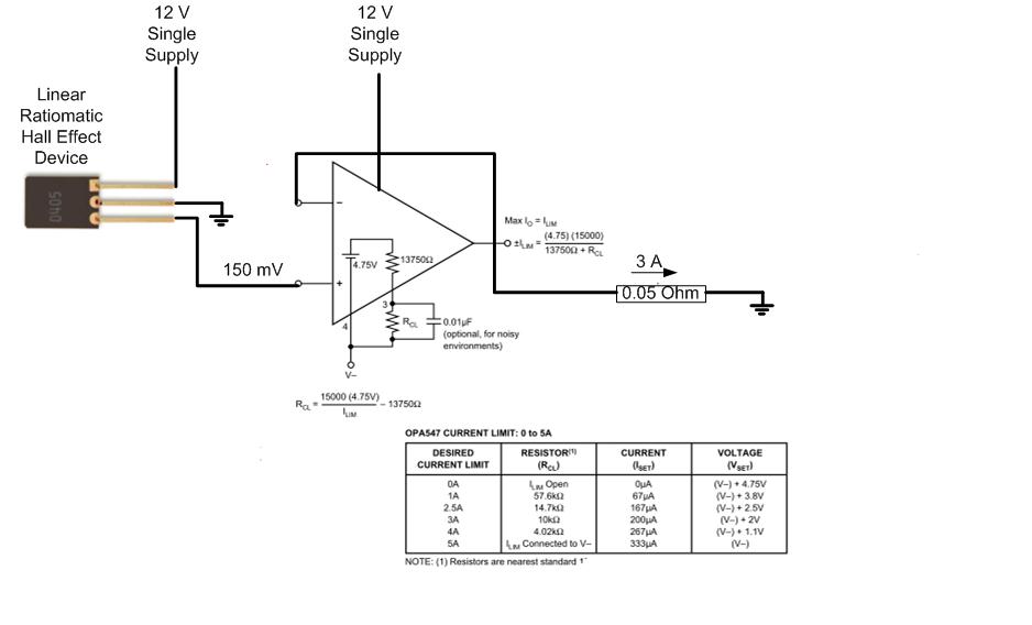
The proposed approach would dissipate (12V)(3A) = 36 watts, which results in significant heat generation in the circuit. This necessitates consideration of two alternatives: 1) Operating the op-amp at a lower supply voltage, if feasible, or 2) Utilizing a...
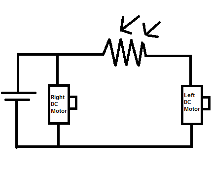
Construct a toy device that spins to the left whenever there is an obstruction in front of it, without utilizing a microcontroller. The proposed design involves using two DC motors as the rear wheels. An LDR (Light Dependent Resistor)...
Warning: include(partials/cookie-banner.php): Failed to open stream: Permission denied in /var/www/html/nextgr/view-circuit.php on line 713
Warning: include(): Failed opening 'partials/cookie-banner.php' for inclusion (include_path='.:/usr/share/php') in /var/www/html/nextgr/view-circuit.php on line 713