
knight Rider 2
The light effect project emulates the iconic scanning LED light sequence featured in the "Knight Rider" television series. The design utilizes a microcontroller, such as an Arduino, to control a series of LED lights arranged in a linear fashion, simulating the movement of light across a surface.
The circuit typically includes the following components: a microcontroller, several high-brightness LEDs, resistors to limit current, and a power supply. The microcontroller is programmed to turn on and off the LEDs in a specific sequence, creating the desired light effect.
An example configuration might involve connecting eight LEDs in a row, each connected to a digital output pin of the microcontroller. Resistors are placed in series with each LED to prevent excessive current flow, ensuring the longevity of the components. The microcontroller's firmware is responsible for the timing and sequencing of the LEDs, allowing for variations in speed and direction of the light movement.
To implement this project, the following steps are generally followed:
1. Design the schematic, ensuring proper connections between the microcontroller, LEDs, and resistors.
2. Write the code that defines the light sequence, including parameters such as delay times and loop iterations.
3. Assemble the circuit on a breadboard or PCB, ensuring that all connections are secure and correctly oriented.
4. Power the circuit and upload the code to the microcontroller, testing the light effect for functionality and making adjustments as necessary.
This project not only serves as a fun homage to the television series but also provides a practical application of basic electronics and programming concepts. It can be expanded by incorporating additional features, such as sound effects or remote control capabilities, further enhancing the user experience.This project describes a light effect that is similar to the one of the car in the TV series `Knight Rider`.. 🔗 External reference
Related Circuits

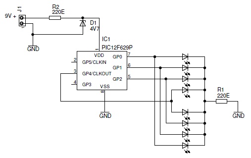
This simple circuit drives six LEDs in a "Knightrider scanner mode." Power consumption primarily depends on the type of LEDs used, particularly when utilizing a 7555 (the CMOS version of the 555 timer). The circuit is designed to create a...
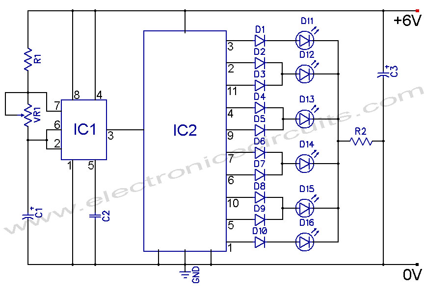
4017 LED Knight Rider Running Light Circuit Diagram. In this 4017 Knight Rider circuit, the 555 timer is configured as an oscillator. It can be adjusted to produce a variety of timing intervals. The 4017 LED Knight Rider circuit utilizes...

The circuit features red lights that chase up and down on the front of the kit, with a pause of about one second between each sequence. Unlike other circuits that continuously pulse a decade counter, this design employs two...

This simple circuit drives six LEDs in a Knight Rider scanner mode. Power consumption primarily depends on the type of LEDs used, especially when utilizing a 7555 (555 CMOS version). The Knight Rider scanner circuit is designed to create a...
This simple circuit drives 6 LEDs in Knightrider scanner mode. Power consumption depends mainly on the type of LEDs used if you use a 7555 (555 CMOS version). More: Note that VDD and GND for the ICs are not...
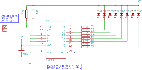
Connect eight LEDs to an Arduino and create a Knight Rider display using only two Arduino pins in this tutorial. This is achieved by utilizing a PCF8574 I/O expander IC. To implement the Knight Rider display using an Arduino and...