
KTM03 type speed control for three-phase half-controlled rectifier circuit
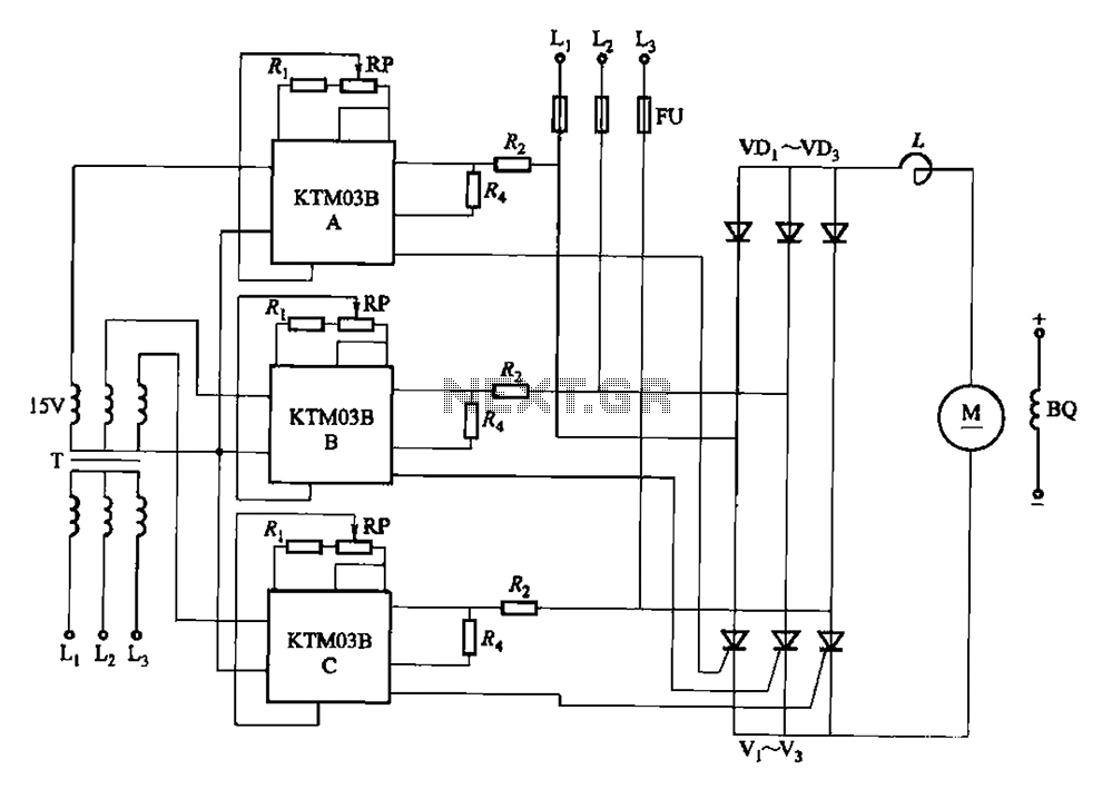
The circuit utilizes a phase control technique to manage the power delivered to a load by varying the conduction angle of thyristors. Each thyristor (V1, V2, etc.) is connected in a configuration that allows for independent control via a potentiometer, specifically RP. By rotating the potentiometer, the phase angle at which each thyristor begins to conduct can be modified.
When the phase angle is adjusted, the point in the AC waveform at which the thyristor turns on is shifted. This results in a change in the effective voltage applied to the load. A smaller conduction angle allows the thyristor to conduct for a shorter duration within each AC cycle, reducing the average voltage and current delivered to the load. Conversely, a larger conduction angle increases the duration of conduction, thereby increasing the average voltage and current.
This method is commonly employed in applications such as light dimmers, motor speed controls, and temperature controllers where precise control of power is required. The design must ensure that the thyristors are capable of handling the load's voltage and current ratings, and appropriate heat sinking may be necessary to dissipate heat generated during operation. Additionally, snubber circuits may be included to protect the thyristors from voltage spikes and to improve the overall reliability of the circuit.
Overall, the ability to adjust the conduction angle through the phase potentiometer provides a versatile means of controlling power delivery in various electronic applications.Adjusting the phase potentiometer RP, can change each corresponding thyristor vl-V. Conduction angle, thereby changing the applied voltage across the load size.
Related Circuits
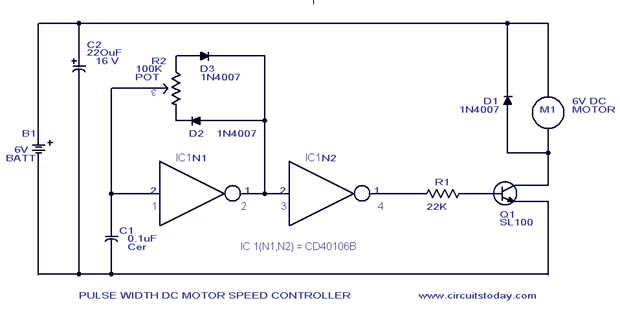
A simple PWM motor speed control circuit with a diagram and schematic for low power DC motors. This easy-to-make PWM DC motor controller is created using the IC CD40106B. The PWM (Pulse Width Modulation) motor speed control circuit utilizes the...
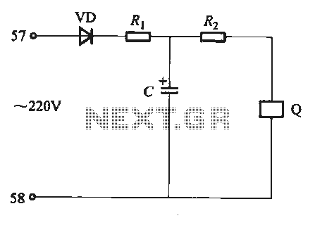
Undervoltage release operates over an extended period. When the power supply voltage drops within the operating voltage range, it triggers the release mechanism, resulting in the rotation of the tripping axle and the disconnection of the circuit breaker. There...
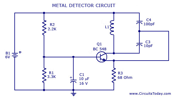
A simple metal detector circuit diagram and schematic using a single transistor and a radio. This metal detector/sensor project is easy to make and is an application of a Colpitts oscillator. The metal detector circuit utilizes a single transistor in...
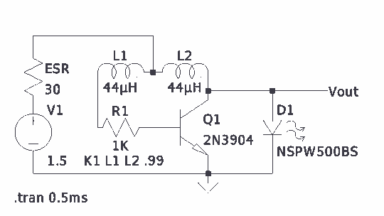
There is much pleasure in useless knowledge. The value of the inductors (44 µH) was determined using an online toroid calculator, specifying an FT-50-43 toroid with 10 turns through it. The described circuit involves the use of an FT-50-43 toroidal...
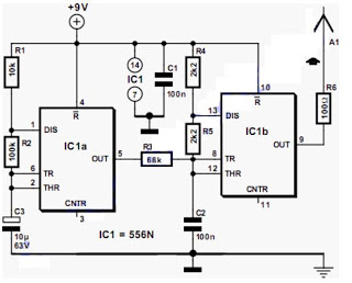
The output frequency alternates between approximately 2100 Hz and 2200 Hz. This unique test signal is easily distinguishable from other potential signals. Resistor R6 is connected to a wire, approximately ten centimeters long, which serves as the antenna. The...
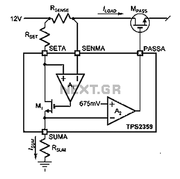
Amplifier A1 utilizes the voltage across the sense resistor sensors to monitor the load current ILOAD. The power management channel employs a similar circuit, with the distinction of integrating resistors RSENSE and RSET. Amplifier A1 is configured to measure the...