
Lab Variable Symmetric Power Supply circuit 2x30V 3.5A
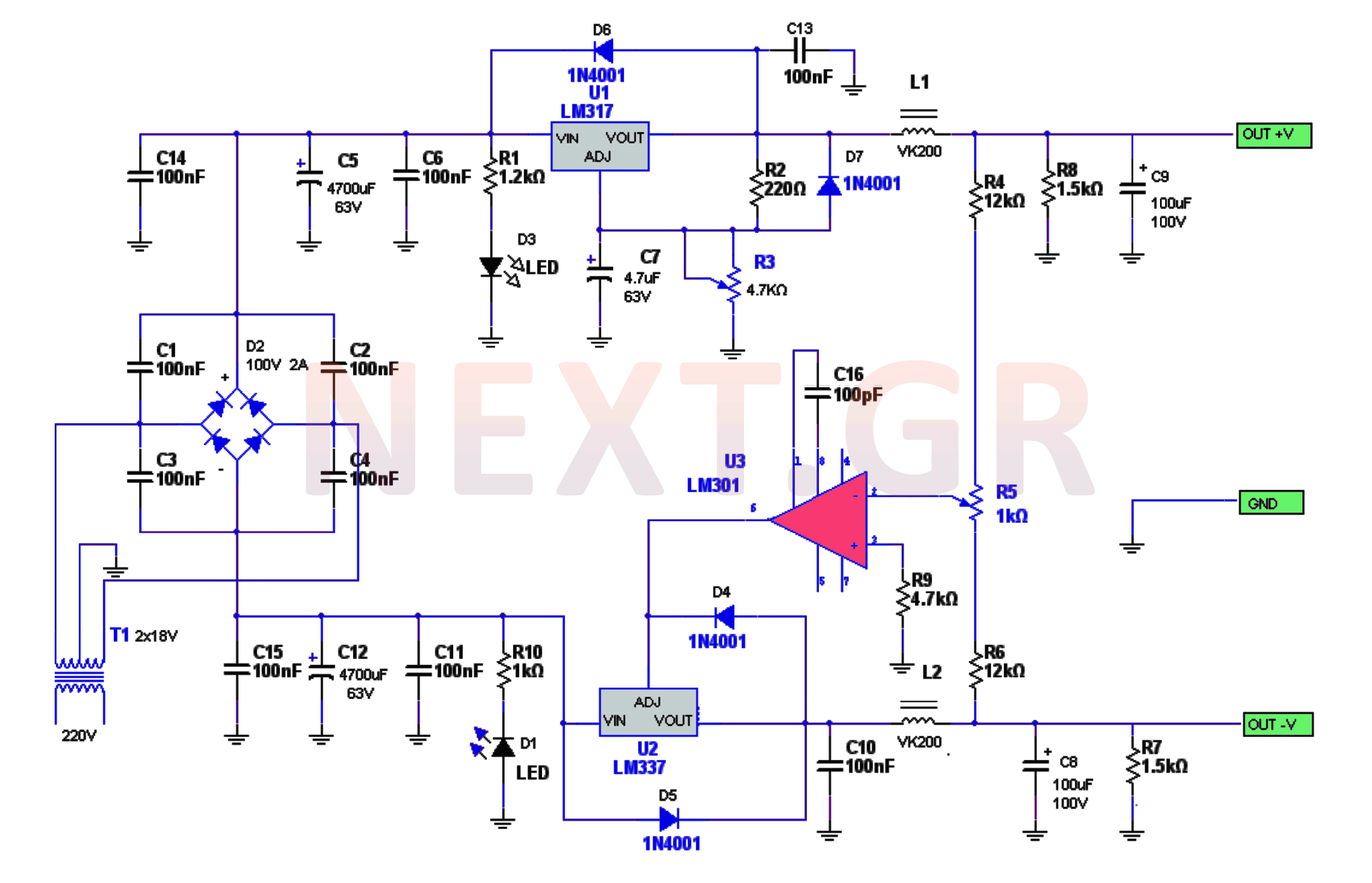
The diodes surrounding the LM317 and LM337 protect these components from potential short circuits at the power supply output or from discharging their electrolytic capacitors, which could cause damage. The positive voltage is adjusted using the potentiometer R3, while the negative voltage is managed by the LM301, which is connected to the non-inverting input through a voltage divider made up of resistors R4, R5, and R6. The inverting input is connected to ground via resistor R9. Any change in the positive voltage triggers an equal variation in the negative voltage.
A capacitor connected to pins 1 and 8 of the power amplifier prevents it from becoming immobilized. The basic resistors at the output serve as a load for circuit operation and help discharge the capacitors once the power supply is turned off. The capacitors in the output lines, along with coils, function as filters to reduce frequency and noise from connected devices.
The RF Ripple Factor is calculated by the formula: RF = VAC / VDC * 100%, where VAC is the AC voltage component (Vpp / 2) corresponding to the specified DC voltage VDC. Given Vpp = 2.24 mV, the peak voltage (Vp) is 1.12 mV, thus VAC = 1.12 mV, and VDC = 10V. The calculation results in a ripple factor RF = (1.12 * 10^-3 V / 10V) * 100% = 0.000112%.
TABLE OF COMPONENTS
CAPACITORS | 1 / 4W RESISTORS | DIODES
--- | --- | ---
C1 = 100nF ceramic<br />C2 = 100nF ceramic<br />C3 = 100nF ceramic<br />C4 = 100nF ceramic<br />C5 = 4700 / 35V Electrolytic<br />C6 = 100nF ceramic<br />C7 = 4.7µF / 400V Electrolytic<br />C8 = 100µF / 35V Electrolytic<br />C9 = 100µF ceramic<br />C10 = 100nF / 100V Electrolytic<br />C11 = 100nF ceramic<br />C12 = 4700 / 35V Electrolytic<br />C13 = 100nF ceramic<br />C14 = 100nF ceramic<br />C15 = 100nF ceramic<br />C16 = 100nF ceramic | R1 = 1.2K<br />R2 = 220Ω<br />R3 = 4.7K Potentiometer<br />R4 = 12K<br />R5 = 1K Potentiometer Trimer<br />R6 = 12K<br />R7 = 1.5K 2W<br />R8 = 1.5K 2W<br />R9 = 4.7K<br />R10 = 1K | D1 = LED Red<br />D2 = 100V 2A Bridge<br />D3 = LED Red<br />D4 = 1N4001<br />D5 = 1N4001<br />D6 = 1N4001<br />D7 = 1N4001
INTEGRATED CIRCUITS | TRANSFORMERS | COILS
--- | --- | ---
U1 = LM317<br />U2 = LM337<br />U3 = LM301 | T1 = 2x18V | L1 = VK200<br />L2 = VK200
This power supply circuit is designed to provide stable and reliable voltage outputs while ensuring protection against potential faults. The careful selection of components and their arrangement allows for efficient noise suppression and voltage regulation, making it suitable for various electronic applications.The power supply circuitry consists of a 220/2 * 18V / 3.5A transformer, a rectifier, a smoothing filter, a power amplifier, LM301, and two regulators LM317 and LM337. The theoretical of the circuit is shown in the figure. The voltage from the transformer is rectified by the rectifying bridge. Parallel to the bridge diodes, C1, C2, C3, C4, have been installed to suppress noise. Then, through the main filter capacitors C5 and C12 and other small capacitances, which further filter the current, it is led to the voltage regulators, consisting of the LM317 & LM337.
These integrated are responsible for regulating the positive and negative tendencies, respectively. In the positive and negative feed lines, LEDs are inserted to show us at any moment that the circuit is being fed correctly.
The diodes around the LM317 & LM337 are used to protect them from accidental short circuits at the output of the power supply or by discharging their electrolytic media, which could damage them.
The positive voltage setting is done with the potentiometer R3, while the negative voltage, which is an LM301. This is connected to the non-inverting input, via a voltage divider, consisting of R4, R5 & R6, to the positive and negative supply voltage.
The inverting input is connected to the earth via a resistor of R9.
If for any reason the positive voltage changes, then the LM301 causes exactly equal variation in the negative supply voltage.
The capacitor connected to the legs 1 and 8 prevents the power amplifier from being immobilized. The basic resistors present at the output serve as a load for the operation of the circuit and for discharging the capacitors after the power supply is switched off.
The capacitors in the positive and negative output lines, as well as the coils, act as frequency and noise cut-off filters from the devices we feed.
The RF Ripple Factor is calculated by:
RF = VAC / VDC * 100%
Where VAC or AC voltage component (Vpp / 2) at the specified DC voltage VDC.
Where Vpp = 2.24 mV thus Vp = 1.12mV or VAC = 1.12mV
And VDC = 10V
RF = (Ripple Factor) = 1.12 * 10-3 V / 10V * 100%
= 1.12 * 10-4 * 100% = 0.000112%
TABLE OF COMPONENTS
| CAPACITORS | 1 / 4W RESISTORS | DIODES |
| C1 = 100nF ceramic C2 = 100nF ceramic C3 = 100nF ceramic C4 = 100nF ceramic C5 = 4700 / 35V Electrolytic C6 = 100nF ceramic C7 = 4.7μF / 400V Electrolytic C8 = 100μF / 35V Electrolytic C9 = 100μF ceramic C10 = 100nF / 100V Electrolytic C11 = 100nF ceramic C12 = 4700 / 35V Electrolytic C13 = 100nF ceramic C14 = 100nF ceramic C15 = 100nF ceramic C16 = 100nF ceramic |
R1 = 1,2K R2 = 220Ω R3 = 4.7K Potentiometer R4 = 12K R5 = 1K Potentiometer Trimer R6 = 12K R7 = 1,5K 2W R8 = 1,5K 2W R9 = 4.7K R10 = 1K |
D1= LED Red D2 = 100V 2A Bridge no. D3 = LED Red D4 = 1N4001 D5 = 1N4001 D6 = 1N4001 D7 = 1N4001 |
| INTEGRATED CIRCUITS | TRANSFORMERS | COILS |
| U1 = LM317 U2 = LM337 U3 = LM301 |
T1 = 2x18V | L1 = VK200 L2 = VK200 |
Related Circuits
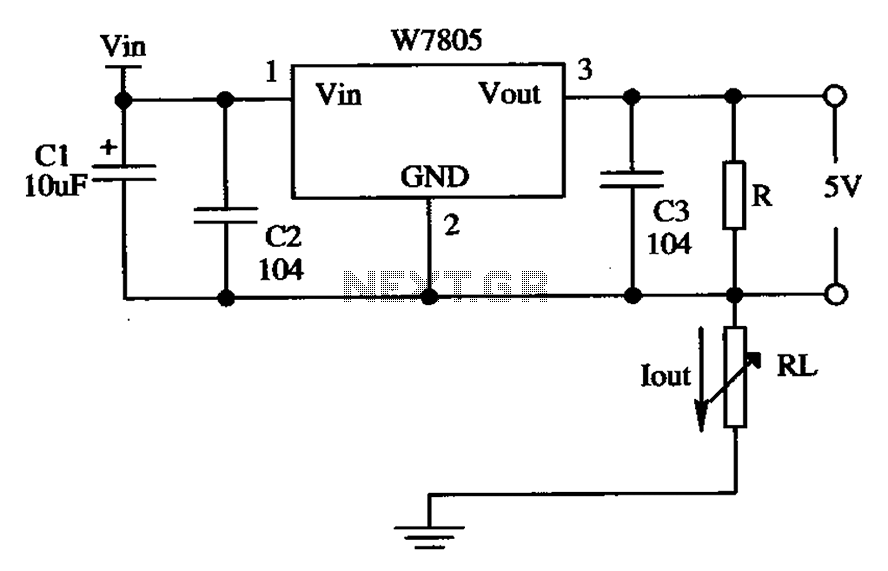
The circuit is composed of a W7805 positive current source application integration circuit that includes a voltage regulator. The W7805 regulator operates in suspension. A resistor is placed between its output terminal and the common terminal, forming a constant...
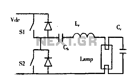
The construction of buildings, when full power is not required, utilizes dimmable electronic ballasts for continuous fluorescent operation, which can further reduce power consumption. Most modern designs and research on electronic ballasts recommend using resonant converter power circuits to...
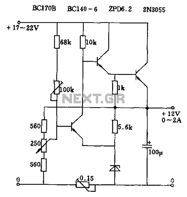
The circuit output voltage can be continuously adjusted from zero to its maximum value. The baseline is established by a constant current sourced from the auxiliary power supply circuit. The reference current of 500 microamperes can be fine-tuned to...
A rain sensor alarm circuit is a useful device for alerting when rainfall occurs. The rain detector circuit presented is straightforward, utilizing only three components while maintaining high sensitivity to detect rain or moisture. The sensor can be constructed...
The telephone repeater is a circuit designed to amplify the call signal, making it louder than the original. This circuit has been developed in response to specific requests. The telephone repeater circuit functions by receiving the incoming audio signal from...
The above picture illustrates an audio logic level probe circuit, which consists of a voltage comparator, a multivibrator, and piezoelectric ceramics (HTD). The multivibrator and piezoelectric components together form the audio circuit, which operates at an audio frequency to...
Warning: include(partials/cookie-banner.php): Failed to open stream: Permission denied in /var/www/html/nextgr/view-circuit.php on line 713
Warning: include(): Failed opening 'partials/cookie-banner.php' for inclusion (include_path='.:/usr/share/php') in /var/www/html/nextgr/view-circuit.php on line 713