
Lantern with dimmer and flasher
The electronic lantern control circuit is designed to enhance the functionality of battery-powered lanterns or flashlights by integrating a dimming and flashing feature. This circuit is particularly beneficial in various scenarios, such as automotive emergencies, camping, and home use. The circuit can operate effectively with battery voltages ranging from 4.5 to 15 volts, allowing for versatility in application.
In the circuit, a key component is the operational amplifier (op-amp), specifically the LM358, which can be replaced with other general-purpose op-amps or comparators without affecting performance. The circuit operates in two modes: dimmer mode and flasher mode, which is controlled by a switch (S1). In dimmer mode, the circuit sends rapid variable-width pulses to the bulb, allowing for brightness adjustment. Conversely, in flasher mode, the circuit generates approximately one pulse per second, providing a flashing effect ideal for signaling or attracting attention.
The TIP32 power transistor is utilized in the circuit to manage the power delivered to the bulb. It operates efficiently by switching on and off, which prevents excessive heat generation compared to traditional rheostatic voltage drop methods. If a higher voltage supply (12-15V) is used, it is recommended to increase the voltage rating of capacitors C1 and C3 to 25V to ensure reliability.
The circuit design allows for component substitution, offering flexibility for users to utilize available parts. For instance, the NPN transistor Q1 (2N4401) can be replaced with other NPN types like the 2N3904 or PN100, while the power transistor Q2 can be substituted with alternatives such as NTE197 or NTE292. Resistor and capacitor values are not critical, allowing for experimentation to achieve desired performance characteristics.
Construction of the circuit can be accomplished on a perf-board, with the option to enclose it in electrical tape for insulation and protection. The design allows for creative adaptations, such as converting traditional gas lanterns to battery-powered models by integrating a bulb socket and a battery compartment, thus expanding the utility of existing equipment.
Overall, the electronic lantern control circuit presents a practical solution for enhancing lighting devices, offering adjustable brightness and signaling capabilities in a compact and efficient design.The electronic lantern control circuit adds high-efficiency dimming and flashing to an existing battery-powered lantern or flashlight or to a custom design. For the car it makes a great lamp for changing a flat tire, back seat reading or emergency engine work.
The flasher mode is useful for warning other drivers of your troubles and it may be adjusted to have a very short flash duration for long-term use as when the car must be left on the shoulder over night.When camping it is great as a low-power night light for the tent or the portable 'potty'--you may select only as much light as you need! The flasher mode is useful for finding a boat dock in the dark or even attracting fish. At home, the flasher is a great way to tell guests when they have found the right house or to "jazz up" battery powered holiday decorations. The circuit is intended for 6 or 12 volt lantern batteries but it should work well with supplies from 4.5 to 15 volts without any modifications to the circuit as shown above.
Except C1/C3. If you intend to use 12 to 15V, increase the working voltage of these two capacitors to 25V instead of the listed 16V. In dimmer mode (switch S1 open), the circuit send rapid variable-width pulses to the bulb to control the brightness and in flasher mode (switch S1 closed) the pulse rate is about one per second.
Very short flashes will give a greatly extended battery life. The TIP32 remains cool since it switches on and off instead of simply dropping the voltage like a power rheostat. The components are not critical and substitutions are fine. Almost any general purpose op-amps or comparators will work in place of the LM358. The two transistors may be replaced by a power FET if desired simply by connecting the gate to pin 7 of the Op-Amp, the source to ground, and the drain to the bulb.
The other end of the bulb connects to the positive terminal of the battery in this case. There is nothing particularly critical about the resistor and capacitor values and the experimenter may change them, if desired. For example, a 10K-pot may be substituted for the 5K by increasing the 3.9K resistors by 2 also (8.2K would be fine).
The 100K's in the flash circuit may be a different value if the capacitors are also scaled (inversely--if the resistors are doubled, the 0.1 and 10uF are halved). For Q1 (2N4401), a PN100 or a BJT like the 2N3904 should work fine also. Power transistor Q2 (TIP32) can be replaced with a NTE197 or a NTE292. Try experimenting with whatever you have at hand or combine values to get the desired value you want.
Construction is not critical - the entire circuit may be built on a piece of perf-board and wrapped with electrical tape. An old gas-mantle lantern could be converted over to battery power by placing a bulb socket in place of the mantle and building a battery compartment in the fuel tank.
Q1 is a NPN audio amp transistor and can be substituted with a 2N3904, PN100, NTE123AP, the BC547, Elector's TUN, etc. Q2 is a PNP power amp and can be substituted with a NTE197. Try others, they also may work. 🔗 External reference
Related Circuits

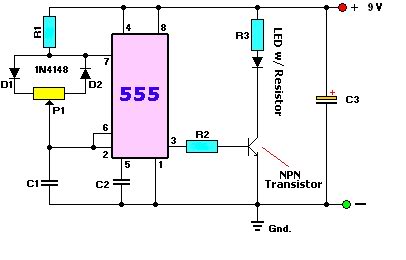
An astable multivibrator, commonly referred to as a free-running multivibrator, is a circuit that generates rectangular waves without the need for external triggering. The timing characteristics of this circuit are determined by the values of the resistors and capacitors...

This circuit utilizes three readily available 555 timer integrated circuits (ICs), all functioning as astable multivibrators. The first 555 timer has both an on period and an off period of 1 second. This IC regulates the on/off intervals of...

The low-cost and compact circuit presented here serves as a highly power-saving flashing LED indicator. While most LEDs typically fail to operate below 2 volts, with a forward voltage of at least 1.6 volts, this flasher can function using...
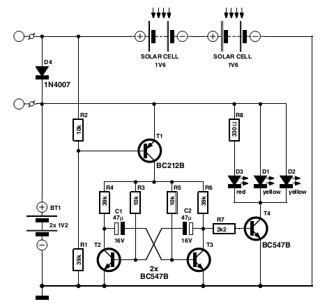
This circuit is designed as a warning flasher to alert road users to dangerous situations in the dark. It can also serve as a bicycle light, subject to traffic regulations and legislation. White LEDs are recommended when the circuit...
The LED flasher circuits operate on a single 1.5-volt battery. The circuit on the upper right utilizes the widely used LM3909 LED flasher integrated circuit (IC) and requires only a timing capacitor and an LED. The LM3909 is a specialized...
A user is new to the forum and has limited experience in DIY electronics. The current project involves creating a battery-powered LED dimmer circuit. The objective of the project is to design a battery-operated LED dimmer circuit that allows for...