
laser gun, detector unit and control pad
The project consists of three integral components: the laser gun assembly, the detector unit, and the control pad.
The laser gun assembly is designed to emit a focused laser beam, which is generated by a laser driver circuit. This circuit typically includes a power source, such as a battery pack, and a laser diode. The laser gun must be ergonomically designed for ease of handling during gameplay, and it should include a trigger mechanism that activates the laser emission when pressed. The power circuit must be efficient to ensure prolonged playtime without frequent battery changes.
The detector unit is responsible for sensing the laser pulses emitted by the opposing player's laser gun. It incorporates a photodiode or phototransistor that is sensitive to the wavelength of the laser used. This unit must be calibrated to detect the laser pulse over a defined area, ensuring that players are rewarded for accurate shots. The detector unit also requires a microcontroller to process incoming signals and determine if a hit has occurred. Upon detecting a laser pulse, the microcontroller will trigger a response in the control pad.
The control pad serves multiple purposes. It keeps track of the score, indicating successful hits and missed shots. It is equipped with an auditory output device, such as a small speaker, to play sound effects that signify a hit. Additionally, the control pad is designed to communicate wirelessly with other control pads using RF (radio frequency) technology. This feature allows for real-time score updates and enhances the multiplayer experience. Each control pad must be programmed to handle incoming signals and update scores accordingly.
The hardware setup should be modular, allowing for easy duplication of components for each player in the game. This modularity is critical for multiplayer scenarios, as it ensures that each player has an independent laser gun and control pad, thus eliminating the need for cumbersome wiring between players. The use of an independent power source for the laser gun enhances portability and user experience.
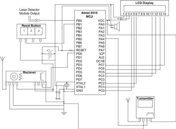
In summary, the project integrates these three components into a cohesive system that facilitates an engaging laser tag experience. Each component must be designed with attention to detail in terms of functionality, user interface, and reliability to ensure a seamless and enjoyable game for all participants.The hardware for this project had three main components: laser gun assembly, detector unit, control pad. The detector units function was to simply detect a laser pulse over a small area sent by the laser driver circuit on the laser gun assembly.
In reaction to this detection the control pad would keep correct score, play a short sound to indicate a hit, and transmit a successful hit via an RF frequency to the other players control pad where it would be received and displayed. These three components joined together would complete the laser transmission, detection, and control for use in a typical laser tag environment; however, due to the multiplayer nature of the game, each hardware component had to be duplicated for the second player to use.
Our general plans was to have a stand-alone laser gun driven by its own independent power source, and have this laser work in conjunction with a combined laser detector and control module. This would allow players to not have the dreaded cable extension f 🔗 External reference
Related Circuits
This circuit uses a sensor made of a small piece of etched PC board and a simple SCR circuit to detect rain and sound a buzzer. The SCR could also be used to activate a relay, turn on a...
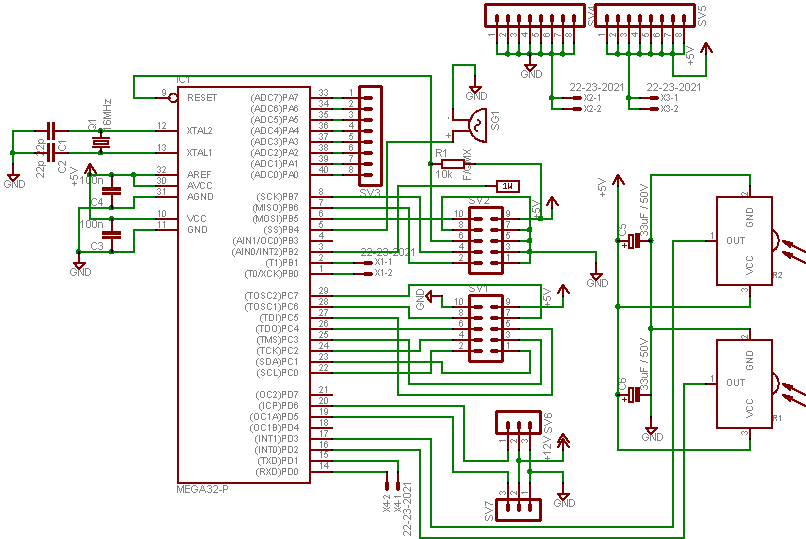
In this project, an ATMEGA16 microcontroller operating at 16MHz will be utilized. To distinguish this project from others, a unique feature has been incorporated: a battery monitoring system. Many robots operate on new or freshly recharged batteries, and if...
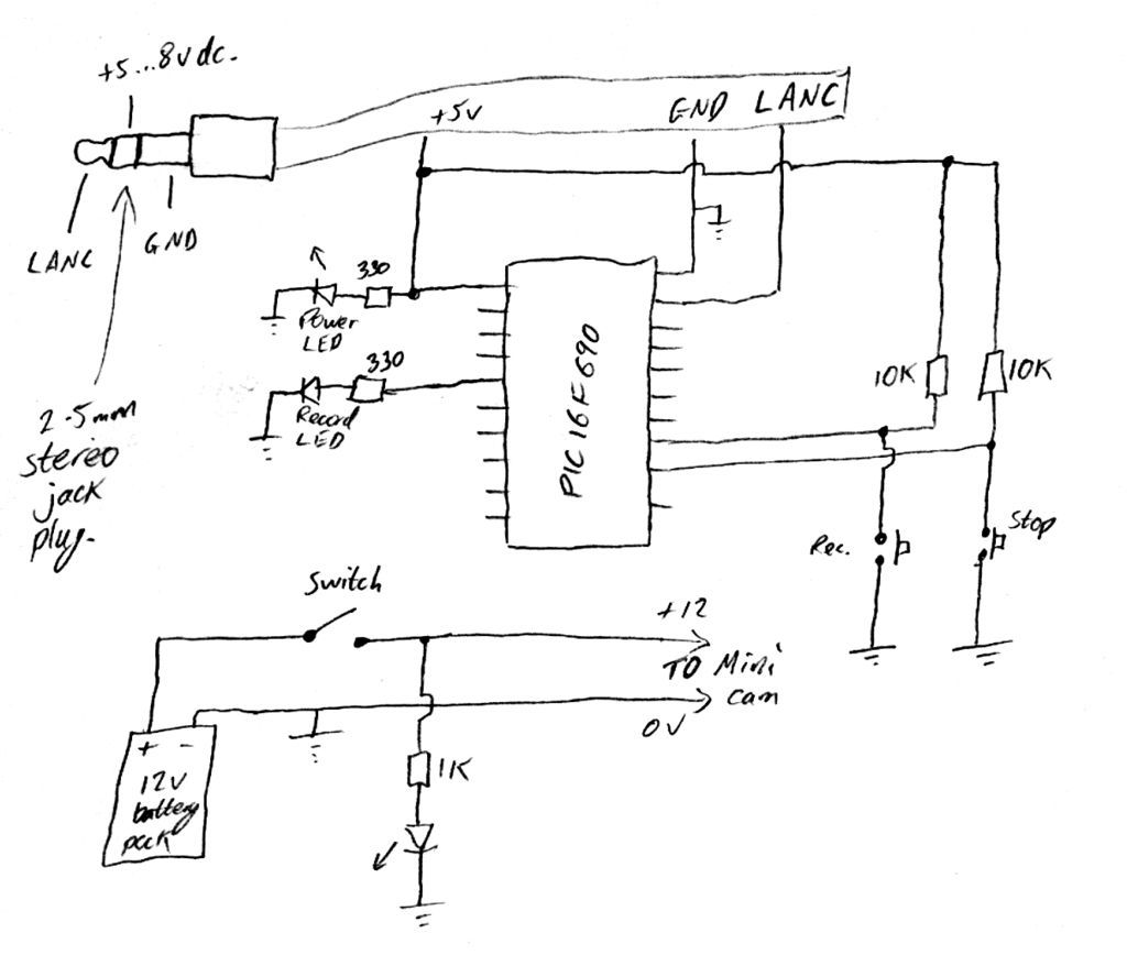
Inexpensive PIC-controlled helmet camera utilizing Sony LANC, suitable for extreme sports. This guide will demonstrate how to create an affordable helmet camera. The proposed electronic schematic involves a PIC microcontroller interfaced with a Sony LANC (Local Application Control Bus) to...
A servo controller has evolved from a "servo slower" unit, designed to reduce the slew rate (traverse time) of proportional servos. In model boats, this device is commonly used to control the rotation of a servo-driven gun turret, as...
This circuit is used to convert a mono audio signal into a stereo signal that can be panned between the left and right channel by a 0-10V control signal, it is intended for analog synthesizer systems. The circuit is...

This design has not been referred to as a GOLD detector, as that term is reserved for more complex devices capable of distinguishing gold from other metals. There is a significant difference between detecting gold and ordinary metals, known...