
Laser Transmitter Circuit
When operating a laser, it is essential to use talkback to coordinate transmissions with other stations, as viewing a laser over long distances through receiving optics can be hazardous. A laser diode may fail while still appearing functional, resulting in an expensive LED with significantly reduced light output and a non-coherent light source. Additionally, as the laser cools during cold winter nights, the light output power may increase, which can lead to potential failures due to excessive output power. For enhanced laser output power, transitioning from laser pointers to laser diodes is necessary, allowing for choices regarding output power and wavelength based on budget considerations.
The circuit employs a 7905 negative voltage regulator, enabling the laser diode's body to connect to ground. Audio is generated by the previously mentioned 4060, with a PNP Darlington transistor configured as a shunt modulator across the laser diode. Two resistors limit the current to the laser diode, with the resistor labeled AOT (adjust on test) requiring careful selection to ensure it provides just below the maximum laser power. The output is set to 10mW, well within the diode's maximum ratings. The audio generation components, including the 4MHz crystal, a 10M resistor, and two 33pF capacitors, are omitted from the schematic for clarity but are consistent with those used in previous circuit descriptions. C6 is a 47uF capacitor, while all other electrolytic capacitors are 10uF, and other capacitors are 10nF. Modulation is applied to the laser through the shunt modulator; when the Darlington transistor conducts, the current supplied from the 7905 and the two resistors is diverted to ground through the transistor and the 10-ohm resistor in its emitter.Two circuits for laser transmitters. The first uses a simple laser pointer module. Any of the normal 3 or 5mW devices will function well. Imports from the USA or Hong Kong are frequently a higher power than the UK approved units. The modules normally contain 2 or 3 1. 5 Volt mercury cells. The external modulated supply should duplicate the voltage used in your particular module. The electronics contained in the module will include the semiconductor laser diode and a constant current source. The ability of the constant current source to be switched on and off at audio frequency will change between manufacturers, but below 1kHz, this is not normally a problem.
However, there are applications where the supply can be switched at 20 to 200kHz and voice or high speed data can be modulated onto this sub-carrier. For these high speed applications the circuit should be tested carefully with an oscilloscope. If unsuitable, the constant current source can be modified or replaced with a circuit that has a faster response.
This circuit uses a crystal and a 4060 oscillator / divider to produce a square wave output in the audio range. In this case a 4MHz crystal giving 488Hz on pin 2. The 5Vp-p square wave is buffered by 3 transistors which includes a totem pole driver. I`ve used two diodesto reduce the voltage by 1. 2V which then supplies the laser module. One switch is attached to the reset pin of the 4060. This is used to select CW ( constant laser output) or Modulated CW. Another switch wired between the key input and ground allows the laser to be keyed via a phono socket or it can be switched permanently on.
This is very useful when aligning the beam onto a distant receiver. Some circuits have been published using 555 timers but I felt that a crystal source would give greater potential for weak signal working. The high accuracy and stability allows the use of DSP software to detect signals below normal noise level.
These programmes are available free via the internet and use your computer`s soundcard to provide the DSP functions. 1) Always use talkback to coordinate transmissions with the other station. Looking at a laser over long distances through your receive optics can be dangerous. 4) A laser diode can fail but still appear to be working. However, what you`ll have is an expensive LED with a light output that is a fraction of the laser and a beam that is not a coherent light source.
5) As the laser cools down on a cold winters night, the light output power will increase. This is not the advantage it first appears as the laser can fail because of excessive output power. If you want to increase your laser output power then you`ll probably have to move on from laser pointers and use a laser diode. Then it`s down to `how much you want to spend`, but at least you get to choose the output power and wavelength.
It uses a 7905 negative voltage regulator so that the body of the laser diode can be connected to ground. The audio is generated by a 4060 as above and a PNP darlington transistor is wired across the laser diode as a shunt modulator.
The circuit uses two resistors to limit the Laser diode current. The resistor labeled AOT (adjust on test) should be selected VERY carefully. It should be the correct value to provide just less than the maximum laser power from the diode. I decided to set the output to 10mW, well inside the max ratings of the diode. Audio is generated by a 4060. The 4MHz crystal, 10M resistor and 2 x 33pF capacitors have been omitted from the diagram for clarity but are the same as used in the other circuit described earlier. C6 is 47uF, all other electrolytics are 10uF. Other capacitors are 10nF. Modulation is applied to the laser via a shunt modulator. When the darlington transistor conducts, the current supplied from the 7905 and the two resistors is shunted to ground through the transistor and the 10 ohm resistor in its emitter.
This circuit ca 🔗 External reference
Related Circuits
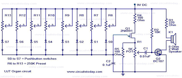
A UJT organ circuit with a circuit diagram is explained in detail. A 2N4891 UJT is used for the operation of the circuit. The UJT (Uni-Junction Transistor) organ circuit is designed to utilize the unique characteristics of the 2N4891 UJT...
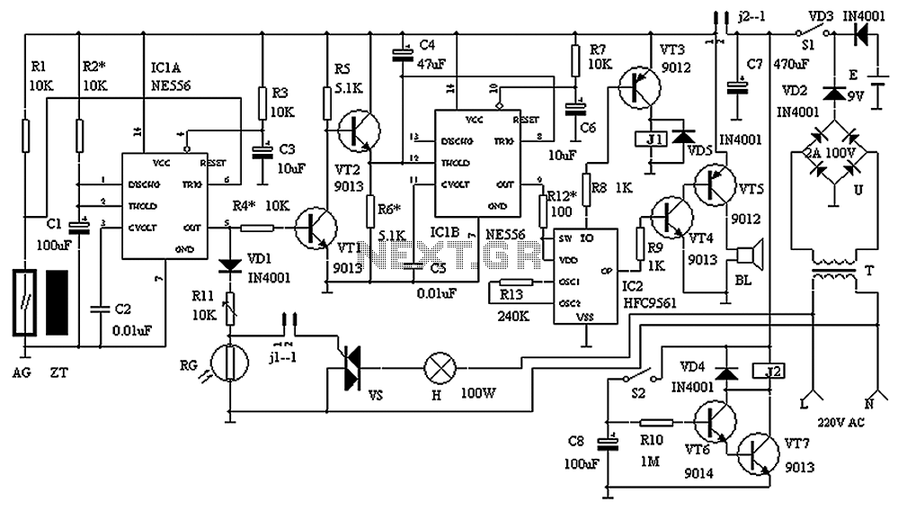
The circuit consists of a triggering device, a monostable delay circuit, an alarm sound generator, an audio amplifier circuit, and a light control circuit, with a partially blocking preset circuit and power circuit. When the door is locked and...
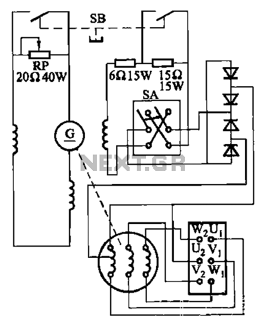
The AX3-300-2 DC arc welding machine circuit is part of the AX, AX1, AX3, and AR series of rotary DC arc welding machines. These machines share a similar structural design, featuring a three-integral unit configuration that combines an inverter...
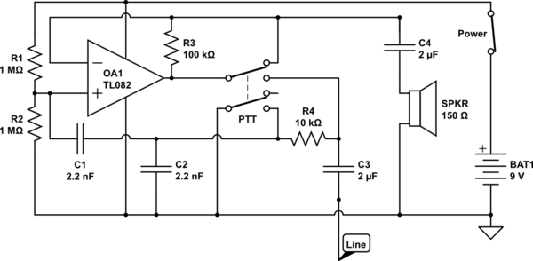
The circuit operates in receive mode, with the Push-To-Talk (PTT) switch enabling transmit mode. The speaker functions as both a microphone and a speaker. Most systems observed utilize a rocking armature transducer for the speaker. There is no base...

This schematic is directly sourced from the Altera ByteBlaster datasheet or manual, which provides comprehensive details regarding the connector's functionality and pin connections. It is advisable to review the datasheet available on their website or through a search engine...
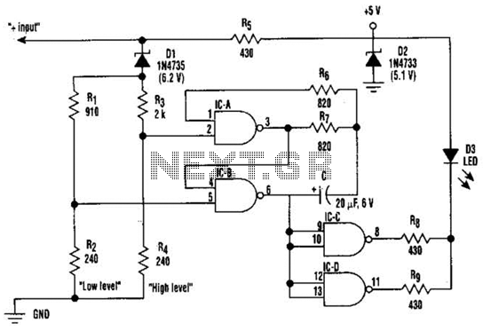
This circuit displays three voltage levels: normal (11 to 15 V), high (greater than 15 V), and low (below 11 V). When the voltage is low, the LED illuminates steadily. In the normal voltage range, the LED remains off....