
Laser1 RoboBrick
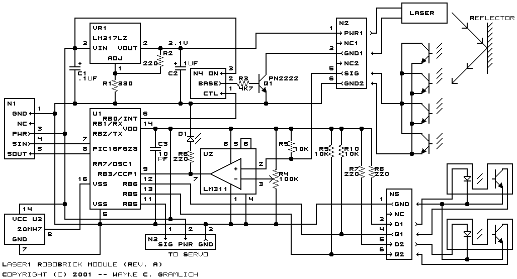
The Laser1 RoboBrick is a module designed to utilize a modified laser pointer for detecting passive reflector beacons at a distance of approximately 10 meters (or about 32 feet). It is intended to be used alongside the LaserHead1 RoboBrick. This module operates on a 3.1-volt power supply that can be controlled programmatically to replace the batteries of the laser pointer. Additionally, the Laser1 RoboBrick can send pulses to a servo, enabling it to move back and forth under program control. When used with three or more appropriately placed passive reflectors, the Laser1 RoboBrick can triangulate a robot's position, though the accuracy will only be determined after construction and testing. The foundational concept of this laser pointer system was inspired by an article by Jim Ubersetzig. Acknowledgment is given to Jim for his initial insights and support during follow-up inquiries. The triangulation equations are detailed in a paper by Clare McGillem and Theodore Rappaport, with a more recent derivation available in a paper by Richard Vannoy. Another relevant paper by M. Bertke and L. Gurvits discusses handling more than three beacons, although the mathematics involved is complex. The McGillem and Gurvits papers were discovered through the bibliography of a comprehensive study on robot navigation by Borenstein, Everett, and Feng. The initial software for the Laser1 RoboBrick will focus on measuring angles between the beacons and the robot. Future software and hardware iterations are expected to compute the robot's (x, y) position based on the (x, y) positions of the beacons. The current limited functionality is due to the floating-point math libraries exceeding the 2K available code space on the PIC16F628; indeed, the code occupies a significant portion of the 8K code space available in the PIC16F876. The design necessitates a servo modified for continuous rotation, allowing the LaserHead1 to sweep a full 360 degrees. An additional sensor is employed to detect each time the LaserHead1 passes a known location. With the Laser1 utilizing a PIC16F628 featuring a 16-bit Timer1 module and PWM/Capture/Compare module, it can resolve the time between beacon reflection returns at an instruction rate of 5 MHz. Given that the current laser head takes 2-3 seconds to complete a 360-degree sweep, a counter resolution of 15 million is required. Since this exceeds 64 thousand, a 24-bit counter is necessary. The system currently operates at 10 MHz, and issues arise when using a 20 MHz crystal, which may indicate a problem with the crystals or the PIC16F628's compatibility with the output voltage levels. There is no evidence that the comparator is functioning effectively, as the return signal is sufficiently clean to be read directly as a binary signal, and the trim pot appears to provide no useful discrimination.
The Laser1 RoboBrick is a sophisticated module that integrates a modified laser pointer for the purpose of detecting passive reflectors, enabling enhanced navigation capabilities for robotic systems. The module's design emphasizes programmability and adaptability, allowing for dynamic control over the laser pointer's power supply and the servo's movement. The system's reliance on triangulation techniques leverages the principles of geometric positioning, where the precise locations of multiple passive reflectors are crucial for accurate robot positioning.
The use of a PIC microcontroller, specifically the PIC16F628, facilitates the execution of timing and control functions necessary for the operation of the Laser1 RoboBrick. The microcontroller's Timer1 module is instrumental in measuring the time intervals between laser reflections, which are critical for triangulation calculations. The implementation of a 24-bit counter is necessary to achieve the required resolution for high-speed measurements, particularly given the sweeping motion of the LaserHead1.
The integration of continuous rotation servos allows for a full 360-degree sweep, which is essential for comprehensive coverage of the detection area. The additional sensor that monitors the servo's position enhances the system's ability to accurately determine the robot's orientation relative to the reflectors. The software's incremental development approach, starting with angle measurements and progressing towards full positional calculations, reflects a systematic methodology in addressing the complexities of robotic navigation.
In conclusion, the Laser1 RoboBrick represents a significant advancement in robotic navigation technology, combining optical detection, precise timing, and programmable control to enable effective triangulation and positioning of robotic systems. The ongoing development and refinement of both hardware and software components will further enhance the capabilities and accuracy of this innovative module.The Laser1 RoboBrick is a module that is designed to allow the use of a slightly modified laser pointer to detect passive refector beacons at a distance of approximately 10 meters (or about 32 feet for the metrically impaired. ) It is meant to be used in conjunction with the LaserHead1 RoboBrick. It has a 3. 1 volt power supply that can be turned on and off under program control to replace the batteries that come with the laser pointer. In addition, the Laser1 RoboBrick can send a pulses to a servo to cause it to slew back and forth under program control. In conjunction with 3 or more properly placed passive reflectors, the Laser1 RoboBrick can be used to triangulate a robot`s position.
We will not know how accurately until after it has been built and tested. The basic idea behind this laser pointer system came from an article written by Jim Ubersetzig [ Ubersitzig1999 ]. We are greatly indebted to Jim for figuring this system out in the first place and for E-mail support as we asked some follow on questions.
The equations for doing triangualation can be found in a paper by Clare McGillem and Theodore Rappaport [ McGillem1989 ]. A more recent on-line derivation of the formulas can be found in a paper by Richard Vannoy [ Vannoy2001 ].
There is another paper by M. Bertke and L. Gurvits [ Bertke1994 ] that explains how to deal with more than three beacons; alas, the math is quite a bit over my head. It should be mentioned that the McGillem and Gurvits papers were found by scanning the bibliography of the fairly comprehensive treatment of robot navigation by Borenstein, Everett, and Feng [ Borenstein1996 ].
The initial software for the Laser1 RoboBrick will only be responsible for measuring the angles between the beacons and the robot proper. The next software/hardware reversion should be able to compute the (x, y) position of the robot, given the (x, y) positions of the beacons.
The reason for the currently reduced functionality is because the floating point math libraries occupy more than the 2K of available code space on PIC16F628; indeed, all of the code appears to occupy a significant fraction of the 8K of code space available in a PIC16F876. The current design requires a servo that has been modified for continuous rotation [ AcronameServo, SandbergServo, Buse2000 ].
This allows the LaserHead1 to sweep a full 360 degrees. An additional sensor is used to detect each time the LaserHead1 sweeps past a known location. Since the Laser1 uses a PIC16F628 with a 16 bit Timer1 module and the PWM/Capture/Compare module, it is capable of resolving the time between the beacon reflection returns to the instruction rate of 5 MHz. Since it takes our current laser head 2-3 seconds to slew 360 degrees, we need a counter resolution of 3G—5G—106 = 15 million.
Since 15 million is greater than 64 thousand, a 24-bit counter is needed. For some reason, the current system only works at 10 MHz. When I plug in one of my 20 MHz crystals, it does not work. Perhaps a bad batch of crystals Perhaps a bad F628 Maybe the F628 does not like the voltage levels coming out of the crystal. Who knows There is no evidence that the comparator is doing any good. The signal the comes back is so clean that it can be read directly as binary signal. There is certainly no evidence that the trim pot is providing any useful descrimination. 🔗 External reference