
lcd interface with microcontroller pic
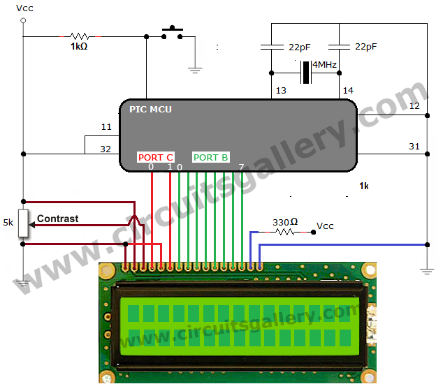
The interfacing of an LCD with a PIC microcontroller typically involves several key components and connections. The LCD module operates in 4-bit mode, which simplifies the wiring and reduces the number of data lines needed for communication. The connections include the data bus lines (D4 to D7) which are linked to specific bits of the PIC microcontroller's Port C, allowing the microcontroller to send data in manageable chunks. The RS (Register Select) pin is crucial for distinguishing between command and data modes; this pin must be controlled correctly to ensure proper functionality.
In practical terms, the setup will include the necessary pull-up resistors on the control lines to ensure stable logic levels. Additionally, a capacitor may be added to the power supply lines of the LCD to filter out noise and provide a stable voltage. The initialization sequence for the LCD must adhere to the timing specifications outlined in the LCD datasheet, ensuring that the device is ready to receive commands after powering on.
The software implementation will involve initializing the LCD library, configuring the microcontroller's ports, and writing functions to handle the sending of data and commands. The commands for clearing the display, setting the cursor position, and writing text will be encapsulated in user-defined functions, promoting code reusability and clarity. This modular approach allows for easy updates and modifications to the display logic without affecting the overall program structure.
In summary, interfacing an LCD with a PIC microcontroller is a well-defined process that combines hardware connections and software programming to achieve effective communication and display capabilities. With careful attention to detail in both the circuit design and coding practices, robust and user-friendly applications can be developed.How to interface LCD (Liquid Crystal Display) display module to PIC microcontroller LCD is a passive component, that is it does not make any light but just modifies the light passing through it for alphanumeric displays. LCD is exclusively manufactured to be used with microcontrollers, which means that it cannot be triggered by usual IC circuits.
This embedded program shows how to connect PIC to LCD display module with microcontroller programming. Here 16G—2 LCD interfaces with the PIC microcontroller. This type of LCD screen can display 2 lines with 16 characters each. Every character consists of 5G—8 or 5G—11 dot matrix. It can display all the letters of alphabet, Greek alphabet, mathematical symbols, punctuation marks etc.
It is also likely to display symbols prepared by the user. Other positive features consist of automatic message shift (left and right), cursor appearance, LED back light etc. Interfacing LCD to microcontroller is quite simple program for beginners and easy to understand. This control line is used to inform the LCD that you are sending in data. To send data to the LCD, put data on the data bus, then makeEN high (1) and wait a little bit and end by bringing EN to low (0) again.
When RS is low (0), the information in the DB0 to DB7 pins are to be considered as an instruction (command- such as Clear screen, Display set, etc. ). When RS is high (1), the information in the DB0 to DB7 pins are to be considered valid text data to print on the LCD screen.
For example, to display the letter i on the screen you should set RS= high. So D0, D1, D2, D3 of LCD display are grounded since connection is 4 bit mode and the D4, D5, D6, D7 are connected to Port C higher bits RC4, RC5, RC6, RC7 respectively. RS pin of LCD module connected to RC2 (PORTC. F2), this will decide whether the LCD inputs are data input or instruction input. In the case of Mikro C compiler we doesn`t bother about this pin, only we need to initialize it as sbit LCD_RS at RC2_bit; rest all the operation done by LCD Library function inside Mikro C.
Enable (EN) pin connected to RC3 (PORTC. F3), a HIGH to LOW transition of this pin needed in order to transfer data or command from PIC to LCD module. As I said above, Mikro C LCD library function will do the job for us. Just initialize the bit as sbit LCD_EN at RC3_bit; The Mikro C PRO for PIC offers a library for communication with LCDSs over the 4-bit interface.
For executing LCD commands we should add this LCD Library file to the program code. Writes text on LCD beginning from definite position. Both string variables and literals can be passed as a text. row: starting position row number column: starting position column number text: text to be written The enable pin of LCD i. e. the 6th pin need a 1 to 0 transition with a small delay in order to process the input lines. That`s why we are providing a small delay in between all functions. 🔗 External reference
Related Circuits
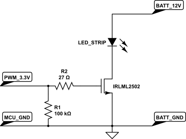
A strip of LEDs is controlled by a microcontroller using pulse-width modulation (PWM) to adjust brightness. The LED strip requires approximately 1.5A at 12V. The user, who has experience only with low-power digital electronics, seeks confirmation of their assumptions...
LCDs are available in various configurations, with the 16x2 matrix display being the most popular. This article demonstrates the interfacing of an ATmega16 microcontroller with an LCD by displaying a simple character. In this project, the LCD operates in...
DC power must be supplied to the instrument through either specialized cabling or an internal battery. This should not be applied to collectible instruments that do not include onboard electronics. It can be conveniently implemented using a field effect...
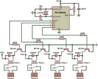
This is a relay driver based on a PIC16F84A microcontroller. The board includes four relays, allowing control of four distinct outputs. The relay driver circuit utilizing the PIC16F84A microcontroller is designed for controlling multiple devices or systems through relay activation....
This project measures the clock pulses supplied to the Timer input of the AVR microcontroller. The Bascom code counts the clock pulses over a duration of 1 second and displays the result. The circuit for this project primarily consists of...
Microchip has announced the availability of new PIC16F1512 and PIC16F151213 XLP microcontrollers. These new XLP (EXtreme Low Power) microcontrollers feature enhanced power management capabilities, making them suitable for battery-operated applications. The PIC16F1512 and PIC16F151213 microcontrollers are designed to operate with...
Warning: include(partials/cookie-banner.php): Failed to open stream: Permission denied in /var/www/html/nextgr/view-circuit.php on line 713
Warning: include(): Failed opening 'partials/cookie-banner.php' for inclusion (include_path='.:/usr/share/php') in /var/www/html/nextgr/view-circuit.php on line 713