
LCD voltmeter circuit
Note: The circuit does not supply an accurate voltage to Vref+, meaning the reading accuracy is contingent on the power supply voltage regulator (not depicted in the circuit diagram), typically a 7805 standard 5V regulator with a 5% accuracy. Consequently, the displayed output may be inaccurate by 5%. To calibrate the output for a more realistic reading, the software's scale factor can be adjusted to correspond with the 7805 output voltage value. A multimeter can be used to measure the power supply voltage (e.g., 4.91V), and instead of the 'ideal' scale factor of 50000L, it can be modified to reflect the multimeter reading, such as using the statement lng = (ADC_ip * 49100L) >> 10. This adjustment scales the maximum ADC output to 4.91V (the maximum reference value), aligning the displayed readings with the multimeter measurements. For production applications, it is advisable to incorporate a voltage reference instead of relying on the regulator for accuracy.
The circuit design involves a PIC microcontroller with an integrated ADC, which continuously samples an input voltage and displays the result on an LCD. The microcontroller is programmed to toggle an LED after each ADC reading, serving as a visual indicator of the system's operational status. The ADC is configured for direct control, bypassing built-in functions to enhance portability across different compiler environments. The fixed-point arithmetic approach is employed to manage memory constraints, particularly beneficial in applications with limited resources.
Calibration is critical for accurate voltage readings. The 7805 voltage regulator's inherent tolerance can lead to discrepancies in the displayed voltage. To achieve precise measurements, the software allows for the adjustment of the scale factor based on actual power supply readings. This ensures that the output displayed on the LCD corresponds accurately to the measured voltage, thus enhancing the reliability of the circuit in practical applications. For enhanced precision in production scenarios, the integration of a dedicated voltage reference is recommended to mitigate the effects of power supply variations.You can use any PIC microcontroller that has an ADC and enough memory to hold the program. The LED is pulsed after every ADC acquisition to indicate that the processor is alive - so you can tell if the software is active. You can recompile the lcd volt meter files if you want examine code operation (using the built in simulator) or change the source code.
Note the hex file is contained in the download. The code is simple showing how to set up the ADC using direct control (it does not use built in routines) so that the code can easily be ported to other compilers. It enters a continuous loop collecting ADC samples and displaying them on the LCD. The only complexity is that the code uses fixed point maths so that it avoids using floating point variables (saving memory space).
Long variables are used to scale the output result. Note: The circuit does not feed in an accurate voltage to Vref+ so the accuracy of the reading is only as good as the power supply voltage regulator (not shown on circuit diagram) - this will usually be a 7805 standard 5V regulator. This has an accuracy of 5% so the displayed output will be wrong by 5%. If you want to calibrate the output to get a more realistic a reading you can set the scale factor in the software to match the 7805 output voltage value.
All you do is use a multimeter to measure the power supply (mine read 4.91V) then instead of the 'ideal' scale factor of 50000L change it to match the multimeter reading e.g. for 4.91V use the statement lng = (ADC_ip * 49100L) >> 10 This scales the maximum ADC output to 4.91 (The maximum reference value) and displayed readings will now match the multimeter readings.
For production use this is not a good idea and you would be better off adding a voltage reference. 🔗 External reference
Related Circuits
The reason why I am using an LCD display is because it allows me to display many characters and it doesn't need to be refreshed as 7-segment LED displays. Also, the interface requires less I/O pins. For this project,...
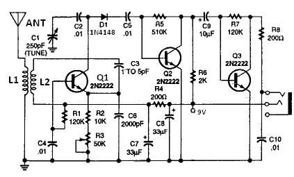
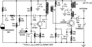
All coils are designed using an inch diameter PVC pipe with 20-gauge insulated hookup wire. L1 requires 6 turns, while L2 requires 14 turns. Additional turns can be added or subtracted from L1 or L2 (or C2 can be...

The utility vehicle anti-theft alarm circuit consists primarily of two main components essential for its operation. The security circuit is activated when the vehicle owner departs from the vehicle, utilizing an anti-theft switch (S B) to engage the alarm...
A circuit involving oscillations is composed of a Houle Wang oscillator that utilizes a transistor configuration with components labeled Ti, n, and n, along with a composition of Q constants for the cycle. The waveform can be modified by...
This sound wattmeter utilizes a series of colored LEDs as a scale to display the relative power output of an amplifier in watts. It is designed for easy integration into a speaker box, requiring only a connection to a...
Clearly indicate on the circuit diagram each type and size of the components. There is a need for assistance in designing a low power FM transmitter circuit, specifically using the BA1404 FM transmitter with a center frequency of 79W...