
LDR Pole Light Switch
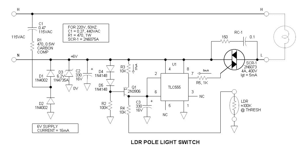
The circuit described integrates several components to form a reliable and efficient lighting control system. The light-dependent resistor (LDR) serves as the primary sensor, detecting ambient light levels to determine when to activate the lighting. The TLC555 timer, configured as a Schmitt trigger, enhances the sensitivity and stability of the light detection process, ensuring that fluctuations in light do not cause erratic switching of the TRIAC. The TRIAC acts as a power switch, allowing for the control of high voltage and current loads with low power control signals. The careful selection of components, such as the LDR and the specific type of TRIAC, demonstrates an understanding of the unique requirements of controlling an incandescent light source while also considering future upgrades to LED technology.
The circuit's design emphasizes safety through the use of an isolation transformer during testing and careful routing of conductors to prevent floating grounds. The use of a current source to bias the LDR not only increases its sensitivity but also stabilizes its performance across varying conditions. The implementation of a Quencharc RC-1 across the TRIAC is crucial for suppressing voltage spikes, which could otherwise damage the circuit or lead to unreliable operation. This comprehensive approach to circuit design ensures that the lighting control system remains functional and safe while accommodating the aesthetic preferences of vintage lighting.My vintage (62 year old) pole light has always been controlled by a timer ”a source of continual frustration due the requirement of readjustment for the ever-changing seasons. However, after knocking it over (I backed my car into it ), I decided it was time for an update. The circuit consists of a light dependent resistor (LDR), TLC555 (applied as Schmitt trigger), and a TRIAC power switch. The complete assembly neatly fits inside the steel pole light tube and the LDR peeks out through a hole in the side. This was really a fun project, and useful to boot. The power supply is the typical capacitor limited charge pump type that is zener regulated at 6. 2V. Due to the lack of isolation, I was careful to identify the return conductor so that the electronics (including the LDR) would not be floating on the hot lead.
For safety, most of the testing was done using an isolation transformer. R1 must absorb a high peak power transient current when power is applied, so a carbon comp, ceramic comp, or wire wound resistor is recommended. Maximum DC current available is 16mA. Actual load is about 6mA. My application was 115V, 60hZ. For 230VAC, the components are indicated on the schematic. In this circuit, +6V is the power return lead, and 0V is the electronic circuit common ”to visualize this, one must screw his head on backwards The light dependent resistor (CdS photocell) that I used was in the TO-5 package that is well adapted for poking through a hole and is held in place with silicone rubber.
The Clairex CL703M19 LDR that I used is no longer available and I have been unable to locate the specs. The DigiKey PDV-P8103-ND appears to be a reasonable choice, but may require bias current tweaking to set the threshold.
A TLC 555 was used as a voltage threshold detecting device with hysteresis. Pin 7 drives the TRIAC gate directly via its open collector output. This is a rather unconventional application. The CMOS version is used to minimize power supply load ”I tried a bipolar 555 and it worked, but the power supply ripple voltage doubled to about 0. 5VP-P. Because the 555 has so much hysteresis, I feared that the ON & OFF thresholds would be too far apart.
To help reduce the hysteresis, the LDR is biased by a current source. Q1 is wired as a current source ”its collector current does not vary with collector voltage. This technique essentially increases the gain of the LDR. The current is set via adjusting the emitter resistor (R3) ”it drops about 0. 37V. The logic TRIAC is an interesting device. It can be triggered by either a positive or negative gate current regardless of voltage blocking polarity. For maximum sensitivity, I used negative gate current. The device I used had an actual Igt (gate current sensitivity) of 1. 5mA that is well below the 5mA Max specification. However, gate overdrive (5mA in my case) is recommended to assure that it fires at low winter temperatures.
Quencharc RC-1 is connected across the TRIAC to help control turn-off voltage transients. For the time being, I am sticking with the vintage incandescent lamp ”it is a matter of aesthetics. I will upgrade to LED technology only when its color balance matches incandescent. 🔗 External reference
Related Circuits
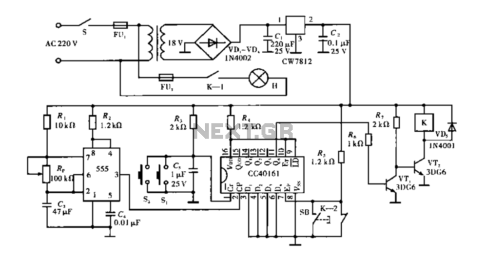
Corridor counter delay circuit for controlling lights. This circuit is tested and functional. When the circuit is energized, the 555 oscillator starts to oscillate. The CC40161 is cleared, and an integrating circuit composed of R3 and C5 transitions the...
The charging circuit automatically stops when the battery is fully charged, allowing the emergency light to remain connected to the AC mains overnight without concern. The circuit consists of two main sections: the inverter and the charger. The inverter...
Constantly changing light and sound analog controller circuit 05 The circuit described is an analog controller designed to modulate light and sound in a dynamic manner. This type of circuit typically employs a combination of resistors, capacitors, and operational amplifiers...
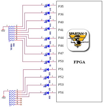
The Spartan-3 board features a traffic light controller utilizing FPGA I/O pins. The traffic light controller card consists of 12 point LEDs arranged in 4 lanes. Each lane is equipped with three LEDs: Go (Green), Listen (Yellow), and Stop...
Disco anyone? Actually, this strobe serves a much more useful purpose than making it look cool when you dance in the dark. You can use it to view fast-moving objects, look for cracks in PC boards (hold the strobe...
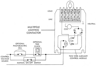
Sensors for lighting controls include photoelectric sensors and presence detectors. Photoelectric sensors typically switch lighting on at dusk and off at dawn, with adjustable settings for sensitivity to light levels. They feature built-in time delays to prevent unwanted switching...