
LED Bar Off Indicator
The circuit operates on the principle of feedback control to manage power consumption effectively. The LM3914 IC serves as the primary driver for the LED bar display, which is typically used for visual representation of signal levels. The inclusion of the additional LED indicator (D11) is a clever design choice that enhances the functionality of the circuit by providing a clear indication of the operational state.
The configuration of transistors T1, T2, and T3 is crucial for the current management system. When all the bar LEDs are off, the absence of voltage across R3 keeps T1 in a non-conducting state, allowing T2 to remain on. This state enables T3 to provide a constant current output through D11, ensuring it lights up and signals that the circuit is still active. Conversely, when any of the bar LEDs (D1 to D10) are illuminated, the voltage across R3 increases, turning T1 on and switching T2 off. This action effectively disables T3, which reduces the current through R2 and thus decreases the overall current draw of the circuit.
The use of a low current draw for the indicator LED (1 mA) is particularly advantageous in battery-operated applications, as it minimizes power consumption while still providing essential feedback about the circuit's status. The design demonstrates a thoughtful balance between functionality and efficiency, making it suitable for a variety of applications where power conservation is a priority. Overall, this indicator circuit is an effective solution for ensuring clear operational feedback while managing power consumption effectively.The simple indicator presented in this article may be combined, in principle, with any circuit that contains an LED bar display driven by a Type LM3914 IC. It ensures that an LED will light when all LEDs driven by the LM3914 are out. This prevents one drawing the erroneous conclusion that, since all the LEDs are out, the circuit is switched off.
T he circuit then continues to draw current, which, especially if it is battery powered, costs unnecessary money, apart from other considerations. The LED in the monitor draws a current of only 1 mA. When the LEDs forming the bar, D1 D10 are all out, there is no potential difference across R3, so that T1 is off and T2 is on.
This results in T3, in conjunction with R5 and the internal reference voltage of IC1, to form a current source that causes a constant current to flow through D11 so that the diode lights. When on of diodes D1 D10 lights, a potential difference ensues across R3, which causes T1 to come on.
This results in T2 being switched off so that there is no collector current through T3. Consequently, there is no feedback at the emitter of T3, so that the current through R2 rises appreciably. The current through R2 determines the current through the LEDs in the bar. Therefore, when T3 is enabled, the current through R2, and thus the total current in the circuit, is reduced considerably.
🔗 External reference
Related Circuits
Useful as a transmitter tune-up meter or an RF sniffer, this is an RF field strength indicator that is loosely based on the Broad Band RF Field Strength Probe, described elsewhere. It detects RF via a square law detector,...
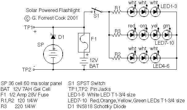
Tired of always spending money on flashlight batteries only to have them fail just when you need them? Try this simple circuit out. It would make an excellent science fair project. The white LEDs are quite bright, they provide...
The heating element is connected in series with two back-to-back 16 amp silicon-controlled rectifiers (SCRs), which are controlled by a small pulse transformer. This pulse transformer features three identical windings: two are dedicated to providing trigger pulses to the...
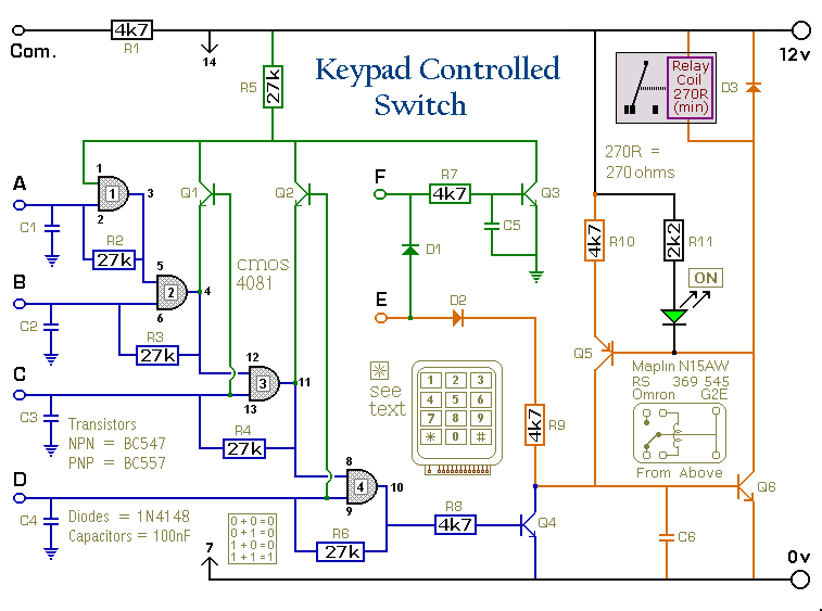
This is a universal version of the four-digit alarm control keypad. The design has been modified to free up the relay contacts, allowing the circuit to function as a general-purpose switch. A single pole changeover (SPCO) or single pole...
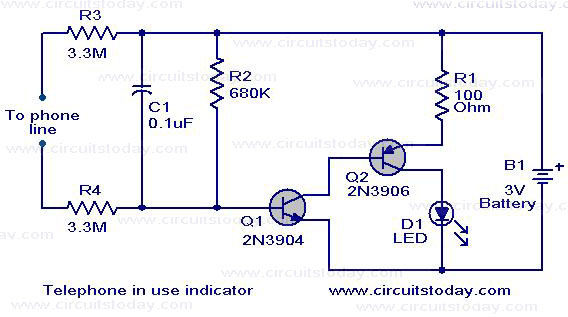
The circuit shown here serves as an indicator for when a telephone receiver is off-hook. It can be integrated with older telephone models that lack this feature. The circuit employs a complementary Darlington pair consisting of Q1 (2N3904) and...
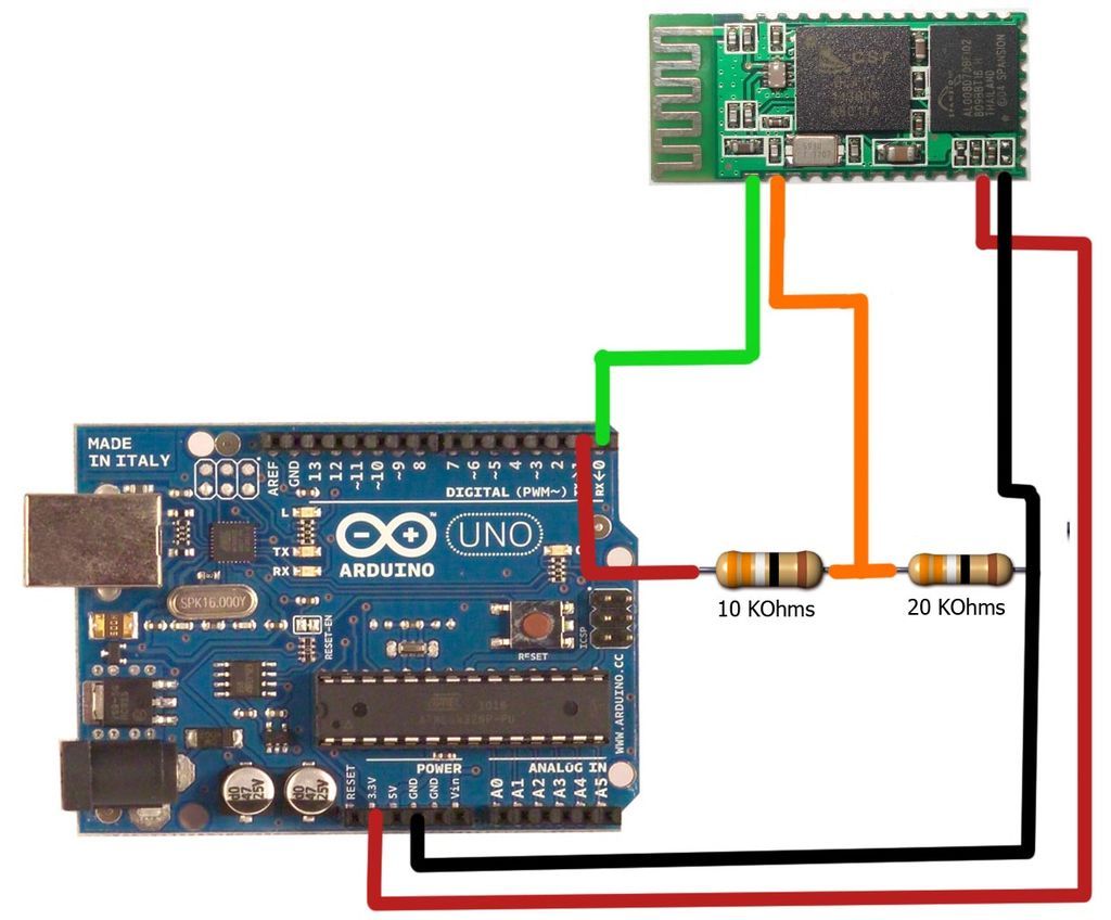
The motion games on the Nokia 5800 sparked an interest in creating a real-world version of a racing car controlled by tilting a phone. The motion-controlled robot, named Hercules due to its high torque and speed, is operated via...