
led blinking using avr studio 5
The ATmega32 microcontroller is a member of the AVR family, widely utilized in embedded systems due to its ease of use and versatility. This tutorial serves as an introductory guide for new users, providing a simple program that demonstrates fundamental concepts of microcontroller programming and operation.
The "Hello World" program typically involves configuring the microcontroller to perform basic input and output operations, such as blinking an LED. This exercise helps users understand the essential components of microcontroller programming, including setting up the development environment, writing code, and uploading it to the microcontroller.
To implement this program, the following steps are generally involved:
1. **Development Environment Setup**: Install the necessary software tools, such as Atmel Studio or Arduino IDE, which are compatible with the ATmega32 microcontroller.
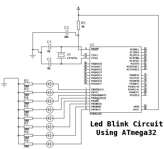
2. **Circuit Design**: Create a simple circuit where an LED is connected to one of the digital output pins of the ATmega32. A current-limiting resistor should be included in series with the LED to prevent damage.
3. **Code Writing**: Write a simple program in C or Assembly language that initializes the microcontroller, configures the designated pin as an output, and toggles the LED state in a loop. This typically involves the following steps:
- Setting the Data Direction Register (DDR) for the pin connected to the LED.
- Using a loop to turn the LED on and off with a delay.
4. **Compiling and Uploading**: Compile the code using the selected development environment and upload it to the ATmega32 microcontroller using a programmer.
5. **Testing**: Power the circuit and observe the LED blinking, confirming that the microcontroller is functioning as intended.
This basic exercise not only introduces beginners to the ATmega32 microcontroller but also lays the groundwork for more complex projects involving sensors, communication protocols, and other peripherals in future applications.This is a very basic tutorial for atmega32 microcontroller beginners to get started. You can call this little program as Hello World for atmega. 🔗 External reference
Related Circuits
The parts to the right of T1 form a simple Joule-thief ('Blocking' oscillator) circuit which boosts the 1.2v supply to 3.5v to operate the LED. C1 is used to extend the charge and discharge cycles to increase brightness and...
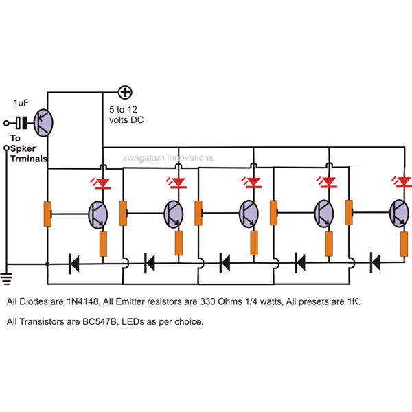
The LEDs in the circuit light up sequentially and "dance" in response to the music level applied at the input, preferably from the speaker terminals of the audio device being monitored. This configuration is consistent across all LEDs in...

A PC’s serial port provides signal lines that you can use to expand the number of input signals. With some additional circuitry tied to these lines, you can use the port to test digital TTL logic-level circuits. You just...

Have you already set up a Christmas tree in your house and decorated it with traditional lights? Build a couple of these LED lights to enhance the Christmas atmosphere. The project involves creating LED lights that can be used to...
Many modern audio recorders are now compatible with digital input S/PDIF (Sony/Philips Digital Interface). Devices like CD changers, MiniDisc recorders, computer sound cards, and the like work with digital signals using the S/PDIF protocol. This digital connection between two...

The circuit below is similar to the one above but can be used with a laser pointer to toggle the relay rather than a push button. The IR photo transistor Q1 (Radio Shack 276-145A) or similar is connected to...