
LED digital Voltmeter
More: Technical Specifications - Characteristics
Supply Voltage: +/- 5 V (Symmetrical)
Power requirements: 200 mA (maximum)
Measuring range: +/- 0-1,999 VDC in four ranges
Accuracy: 0.1%
FEATURES
- Small size
- Easy construction
- Low cost
- Simple adjustment
- Easy to read from a distance
- Few external components
How it Works
In order to understand the principle of operation of the circuit it is necessary to explain how the ADC IC works. This IC has the following very important features:
- Great accuracy
- It is not affected by noise
- No need for a sample and hold circuit
- It has a built-in clock
- It has no need for high accuracy external components
An Analogue to Digital Converter, (ADC from now on) is better known as a dual slope converter or integrating converter. This type of converter is generally preferred over other types as it offers accuracy, simplicity in design and a relative indifference to noise which makes it very reliable. The operation of the circuit is better understood if it is described in two stages. During the first stage and for a given period the input voltage is integrated, and in the output of the integrator at the end of this period, there is a voltage which is directly proportional to the input voltage. At the end of the preset period, the integrator is fed with an internal reference voltage and the output of the circuit is gradually reduced until it reaches the level of the zero reference voltage. This second phase is known as the negative slope period and its duration depends on the output of the integrator in the first period. As the duration of the first operation is fixed and the length of the second is variable it is possible to compare the two and this way the input voltage is in fact compared to the internal reference voltage and the result is coded and is sent to the display.
All this sounds quite easy but it is in fact a series of very complex operations which are all made by the ADC IC with the help of a few external components which are used to configure the circuit for the job. In detail, the circuit works as follows. The voltage to be measured is applied across points 1 and 2 of the circuit and through the circuit R3, R4, and C4 is finally applied to pins 30 and 31 of the IC. These are the input of the IC as you can see from its diagram (IN HIGH & IN LOW respectively). The resistor R1 together with C1 are used to set the frequency of the internal oscillator (clock) which is set at about 48 Hz. At this clock rate, there are about three different readings per second. The capacitor C2, which is connected between pins 33 and 34 of the IC, has been selected to compensate for the error caused by the internal reference voltage and also keeps the display steady. The capacitor C3 and the resistor R5 are together the circuit that does the integration of the input voltage and at the same time prevent any division of the input voltage making the circuit faster and more reliable as the possibility of error is greatly reduced. The capacitor C5 forces the instrument to display zero when there is no voltage at its input. The resistor R2 together with P1 are used to adjust the instrument during set-up so that it displays zero when the input is zero. The resistor R6 controls the current that is allowed to flow through the displays so that there is sufficient brightness without damaging them. The IC, as already mentioned above, is capable of driving four common anode LED displays. The three rightmost displays are connected so that they can display all the numbers from 0 to 9 while the first from the left can only display the number 1 and when the voltage is negative the “-” sign. The whole circuit operates from a symmetrical ±5 VDC supply which is applied at pins 1 (+5 V), 21 (0 V), and 26 (-5 V) of the IC.This is an easy to build, but nevertheless very accurate and useful digital voltmeter. It has been designed as a panel meter and can be used in DC power supplies or anywhere else it is necessary to have an accurate indication of the voltage present. The circuit employs the ADC (Analogue to Digital Converter) I.C. CL7107 made by INTERSIL. This IC incorporates in a 40 pin case all the circuitry necessary to convert an analogue signal to digital and can drive a series of four seven segment LED displays directly.
The circuits built into the IC are an analogue to digital converter, a comparator, a clock, a decoder and a seven segment LED display driver. The circuit as it is described here can display any DC voltage in the range of 0-1999 Volts. Technical Specifications - Characteristics Supply Voltage: ............. +/- 5 V (Symmetrical) Power requirements: ..... 200 mA (maximum) Measuring range: .......... +/- 0-1,999 VDC in four ranges Accuracy: ....................... 0.1 % FEATURES - Small size - Easy construction - Low cost. - Simple adjustment. - Easy to read from a distance. - Few external components. How it Works In order to understand the principle of operation of the circuit it is necessary to explain how the ADC IC works. This IC has the following very important features: - Great accuracy. - It is not affected by noise. - No need for a sample and hold circuit. - It has a built-in clock. - It has no need for high accuracy external components. An Analogue to Digital Converter, (ADC from now on) is better known as a dual slope converter or integrating converter.
This type of converter is generally preferred over other types as it offers accuracy, simplicity in design and a relative indifference to noise which makes it very reliable. The operation of the circuit is better understood if it is described in two stages. During the first stage and for a given period the input voltage is integrated, and in the output of the integrator at the end of this period, there is a voltage which is directly proportional to the input voltage.
At the end of the preset period the integrator is fed with an internal reference voltage and the output of the circuit is gradually reduced until it reaches the level of the zero reference voltage. This second phase is known as the negative slope period and its duration depends on the output of the integrator in the first period.
As the duration of the first operation is fixed and the length of the second is variable it is possible to compare the two and this way the input voltage is in fact compared to the internal reference voltage and the result is coded and is send to the display. All this sounds quite easy but it is in fact a series of very complex operations which are all made by the ADC IC with the help of a few external components which are used to configure the circuit for the job.
In detail the circuit works as follows. The voltage to be measured is applied across points 1 and 2 of the circuit and through the circuit R3, R4 and C4 is finally applied to pins 30 and 31 of the IC. These are the input of the IC as you can see from its diagram. (IN HIGH & IN LOW respectively). The resistor R1 together with C1 are used to set the frequency of the internal oscillator (clock) which is set at about 48 Hz.
At this clock rate there are about three different readings per second. The capacitor C2 which is connected between pins 33 and 34 of the IC has been selected to compensate for the error caused by the internal reference voltage and also keeps the display steady. The capacitor C3 and the resistor R5 are together the circuit that does the integration of the input voltage and at the same time prevent any division of the input voltage making the circuit faster and more reliable as the possibility of error is greatly reduced.
The capacitor C5 forces the instrument to display zero when there is no voltage at its input. The resistor R2 together with P1 are used to adjust the instrument during set-up so that it displays zero when the input is zero. The resistor R6 controls the current that is allowed to flow through the displays so that there is sufficient brightness with out damaging them.
The IC as we have already mentioned above is capable to drive four common anode LED displays. The three rightmost displays are connected so that they can display all the numbers from 0 to 9 while the first from the left can only display the number 1 and when the voltage is negative the «-« sign. The whole circuit operates from a symmetrical ? 5 VDC supply which is applied at pins 1 (+5 V), 21 (0 V) and 26 (-5 V) of the IC. 🔗 External reference
Related Circuits
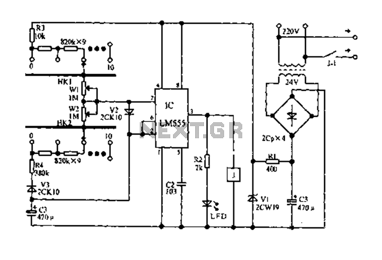
The circuit diagram for an electric start and stop timer is illustrated in the following cycle. It utilizes the LM555 integrated circuit configured as an adjustable duty cycle multivibrator. The circuit includes components C3, KH1, W1, KH2, and W2,...
The project began as a simple variac (variable autotransformer) and electrical outlet mounted on a wooden block. Eventually, it was housed in the case of an old audio signal generator for improved safety and aesthetics. A 0-250VAC analog meter...
The voltage that controls a V/F converter will be displayed when a frequency counter is used, which is directly proportional to the input voltage over a 1-second interval. A Voltage-to-Frequency (V/F) converter is a critical component in various electronic applications,...
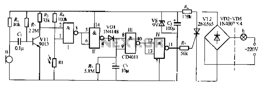
The CDI011 integrated circuit is designed for a sound and light-controlled stair delay switch circuit, which is relatively simple and effective. It utilizes a combination of NAND gates and differential input dynamics. The circuit has two input terminals; when...
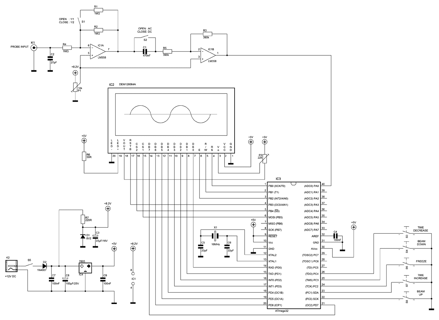
A few months ago as I was surfing on the net, I saw an oscilloscope based on PIC18F2550 microcontroller and a KS0108 controller based graphical LCD. That was Steven Cholewiak's web site. I had never seen before so amazing...
The following are current regulator circuits that can be used to drive light emitting diodes. As always, take time to do some testing before attempting to use these circuits in actual applications. Current regulator circuits are essential for controlling the...