
LED Hat Display with Pong using an Arduino
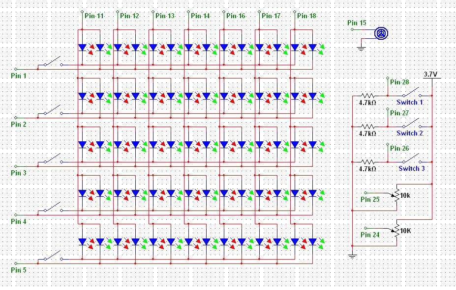
To create a Pong game using a 5G-7 LED display, the initial setup involves carefully soldering the necessary connections. The display consists of multiple segments that need to be wired correctly to ensure proper functionality. Each row of the LED display will require a connection to a DIP switch, which allows for toggling between two colors. The schematic provided serves as a visual guide, indicating the correct pin assignments and connections for the microcontroller.
The microcontroller, typically an Arduino, must be securely mounted onto a breadboard. Power connections to the microcontroller are essential for operation, with each pin needing to be connected to the appropriate voltage source. For clarity, the schematic outlines the power distribution, ensuring that the microcontroller receives the necessary power supply for its operation.
When connecting the LED display to the breadboard, it is crucial to follow the schematic closely. Each output pin from the microcontroller corresponds to a specific segment of the LED display, allowing for the display of game graphics. The wiring must be precise to avoid any malfunction during gameplay.
For the DIP switches, they act as inputs to control different aspects of the game. Each switch connects to a microcontroller pin and the positive voltage, enabling the microcontroller to read the switch status. To ensure signal integrity and prevent floating inputs, a resistor is connected from each input pin to ground. This configuration provides a stable low signal when the switch is not activated.
Overall, this project combines hardware assembly with programming, where the microcontroller interprets the switch inputs and manages the LED display output to create an interactive Pong game experience. Proper attention to detail in the wiring and connections will lead to a successful implementation of the game on the hard hat display.A while ago, as my first microcontroller project, I made a Pong game on a 5G—7 LED display, but then nothing became of it. Recently I was given a hard hat as part of a uniform (for an engineering competition) and told to customize it, and remembered pong.
For the first step, you need to solder wires to the display. You will also need to solder one switch from the dip switch between the two colours` cathodes for each row. To make it clearer I have attached a schematic of the display in the pictures (click the [i] on the picture to get the full sized version). For this step you need to solder the microcontroller socket to the breadboard. Then solder all of the power connections to the microcontroller socket pins. If you are unsure which pins to solder, there is a good reference here. Now you need to attach the wires coming off the LED display to the breadboard. To help with this see the attached schematic, or you can look in the code in the intro to find the output pins on the arduino.
For each switch, it is one contact of the switch connected to the corresponding microcontroller pin and the other to the positive voltage. There is also one resistor from the input pin to ground for each switch. 🔗 External reference
Related Circuits
This is a simple LED circuit that takes power from the USB port. I needed this USB light since long time ago but, finally, I was able to build it. The circuit schematic is so simple: Just one resistor...
I like to see lights move to music. This project will indicate the volume level of the audio going to your speakers by lighting up LEDS. The LEDS can be any color so mix them up and really make...
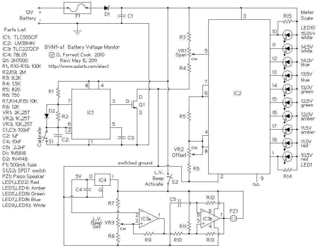
This is a low power voltmeter circuit that can be used with alternative energy systems that run on 12 and 24 volt batteries. The voltmeter is an expanded scale type that indicates small voltage steps over the 10 to...
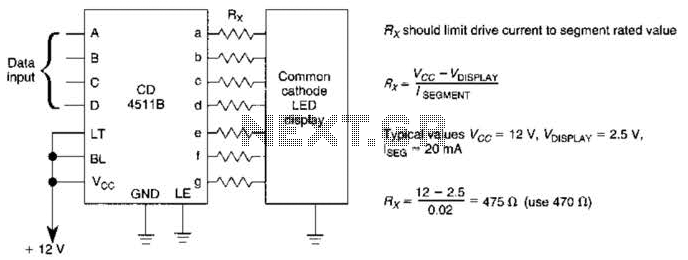
A CD4511B CMOS LED display driver can be utilized to operate a common cathode LED display. Current limiting resistors are employed to restrict the segment current to the specified value at the maximum supply voltage. The CD4511B is a...
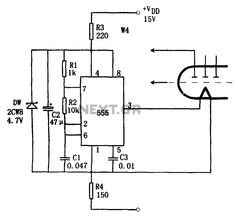
The economic fluorescent display circuit is illustrated in the figure. The primary component of this circuit is the 555 timer configured as a multivibrator. The oscillation frequency is determined by the components R1, R2, and C1, with a frequency...
The character data and command from the microcontroller is transferred serially to a shift register (74HC595), and the parallel output from the shift register is fed to LCD pins. 74HC595 is a high-speed 8-bit serial in, serial or parallel-out...